Evaluation method and manufacturing method of light-emitting element material, manufacturing method of light-emitting element, light-emitting element, and light-emitting device and electric appliance having light-emitting element
a technology of light-emitting elements and manufacturing methods, which is applied in the field of evaluation methods of light-emitting elements, can solve the problems of unfavorable reliability of light-emitting elements, especially reliability of a life-time of light-emitting elements, and achieve the effect of low cos
- Summary
- Abstract
- Description
- Claims
- Application Information
AI Technical Summary
Benefits of technology
Problems solved by technology
Method used
Image
Examples
embodiment mode 1
[0039]An example of an evaluation method for a light-emitting element material according to the present invention is described.
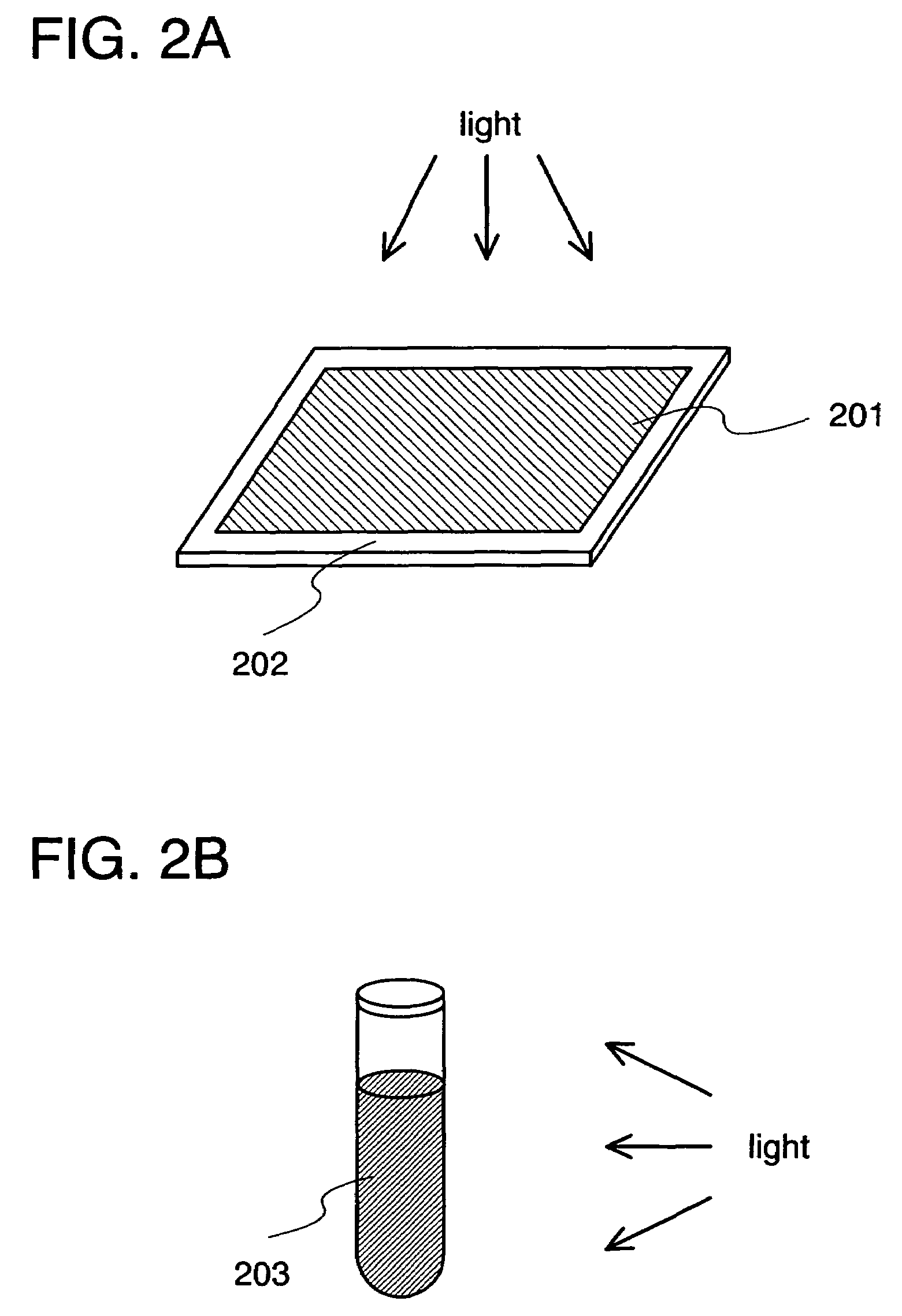
[0040]For the evaluation, a substrate 201 with a film 202 formed from a light-emitting element material shown in FIGS. 2A and 2B may be used. For the substrate 201, a material such as quartz or glass which transmits light with a wavelength of 300 nm or more, may be used. In addition, a solution 203 in which a light-emitting element material is dissolved may be used as a sample. In this case, methylene chloride, chloroform, or the like is preferably used as a solvent for dissolving the light-emitting element material.
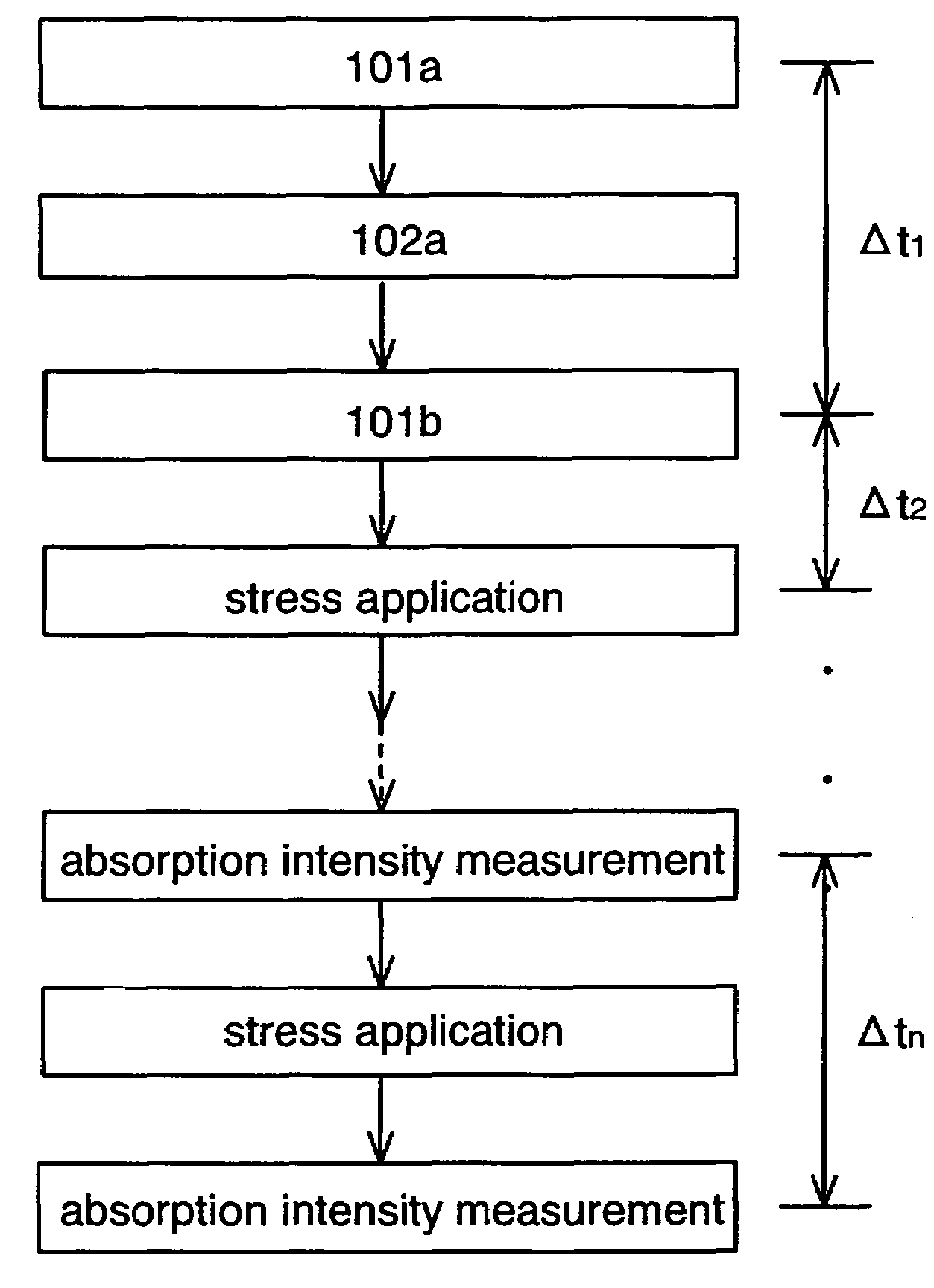
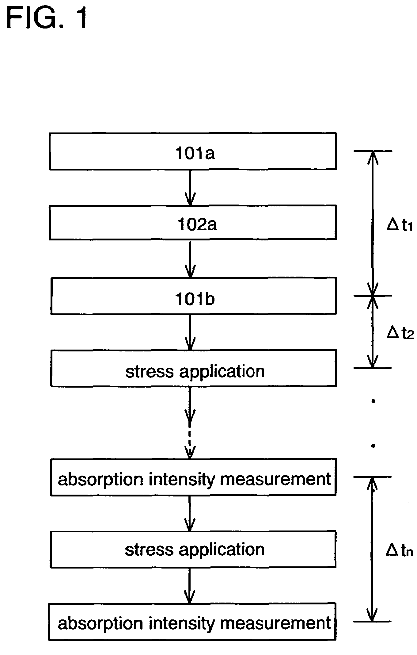
[0041]A measurement method of photochemical stability is described with reference to FIG. 1. First the sample is irradiated with light and an absorption spectrum is measured to measure absorption intensity for an arbitrary wavelength in an ultraviolet region in an initial state (an absorption intensity measurement 101a). Then, the sample is irrad...
embodiment mode 2
[0045]In this embodiment mode, an example of a light-emitting element which is manufactured using a light-emitting element material defined to be suitable for a host material or a guest material by the evaluation method in Embodiment Mode 1 is described with reference to FIG. 3.
[0046]FIG. 3 shows a light-emitting element which has a light-emitting layer 313 between a first electrode 301 and a second electrode 302. The light-emitting layer 313 contains a light-emitting element material which is manufactured through a process of evaluating photochemical stability by an evaluation method of a light-emitting element material according to the present invention.
[0047]In such a light-emitting element holes injected from the first electrode 301 and electrons injected from the second electrode 302 are recombined in the light-emitting layer 313. Then, a guest is excited. The guest of the present invention in the excited state emits light when returning to a ground state. Note that the guest c...
embodiment mode 3
[0060]Since a change in luminance with light-emitting time is small in the light-emitting element of the present invention described in Embodiment Mode 2, a light-emitting device capable of displaying an image favorably for a long time can be provided.
[0061]In this embodiment mode, a circuit structure and a driving method of a light-emitting device having a display function will be described with reference to FIGS. 4 to 7.
[0062]FIG. 4 is a schematic top view of a light-emitting device to which the present invention is applied. In FIG. 4, a pixel portion 6511, a source signal line driver circuit 6512, a writing gate signal line driver circuit 6513, and an erasing gate signal line driver circuit 6514 are provided over a substrate 6500. The source signal line driver circuit 6512, the writing gate signal line driver circuit 6513, and the erasing gate signal line driver circuit 6514 are each connected to an FPC (flexible printed circuit) 6503 which is an external input terminal, through ...
PUM
| Property | Measurement | Unit |
|---|---|---|
| wavelength | aaaaa | aaaaa |
| wavelength | aaaaa | aaaaa |
| wavelength region | aaaaa | aaaaa |
Abstract
Description
Claims
Application Information
 - R&D
- Intellectual Property
- Life Sciences
- Materials
- Tech Scout
- Unparalleled Data Quality
- Higher Quality Content
- 60% Fewer Hallucinations
Browse by: Latest US Patents, China's latest patents, Technical Efficacy Thesaurus, Application Domain, Technology Topic, Popular Technical Reports.
© 2025 PatSnap. All rights reserved.Legal|Privacy policy|Modern Slavery Act Transparency Statement|Sitemap|About US| Contact US: help@patsnap.com


