Cooled high power vehicle inductor and method

a high-power vehicle and inductor technology, which is applied in the direction of transformer/react mounting/support/suspension, transformer/inductance details, electrical equipment, etc., can solve the problems of limiting heat dissipation and net braking force of the vehicle, and achieve the effect of reducing the size and weight requirement (“footprint”), reducing the footprint, and reducing the footprin

Inactive Publication Date: 2009-03-24
SHEPPARD MULLIN RICHTER & HAMPTON
View PDF13 Cites 16 Cited by
  • Summary
  • Abstract
  • Description
  • Claims
  • Application Information

AI Technical Summary

Benefits of technology

[0014]The benefits of the cooled inductor may be realized in a pure performance improvement and / or a reduced size and weight requirement (“footprint”) of the components. With a reduced footprint, the vehicle integrator has more options in the cooled inductor's placement, and may even incorporate it into a separate existing component (e.g., the inverters). Furthermore, this method of providing the vehicle with a cooled DC-DC converter (inductor) is amenable to low cost manufacture, which will be described further below. Heavy duty HEVs such as metropolitan transit buses may especially benefit, as maximum performance, here, is coupled to a lighter device having maximum efficiency, and as incremental improvements in this field may result in appreciable accumulated operational cost savings.

Problems solved by technology

This torque results in a net braking force on the vehicle.
However, under the conditions of a heavy duty HEV / EV, the dissipation of heat is a limiting factor of an inductor's / inductor-based high power component's performance.

Method used


Image

  • Cooled high power vehicle inductor and method
  • Cooled high power vehicle inductor and method
  • Cooled high power vehicle inductor and method

Examples


Embodiment Construction

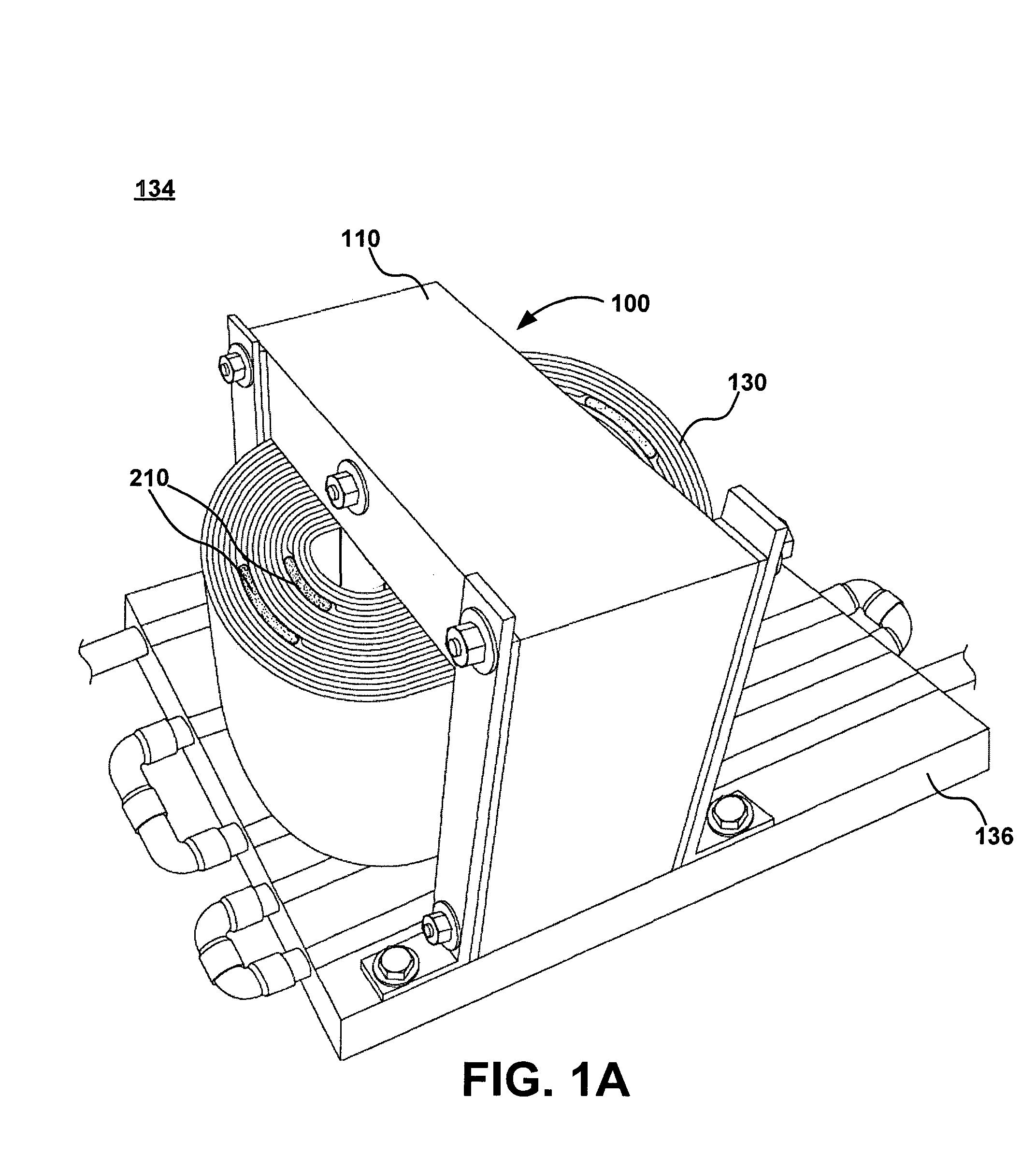
[0047]With reference to FIGS. 1A-1C and 22, an embodiment of a cooled high-power vehicle inductor 100, 2100 specially adapted for hybrid electric vehicles (HEVs) and electric vehicles (EVs) will be described. In the embodiment shown, the high-power inductor 100, 2100 is associated with a DC-to-DC converter in an inverter-DC buss boost circuit; however, in alternative embodiments, the cooled high-power vehicle inductor 100 may have a different construction and / or be used in a different application on the vehicle.

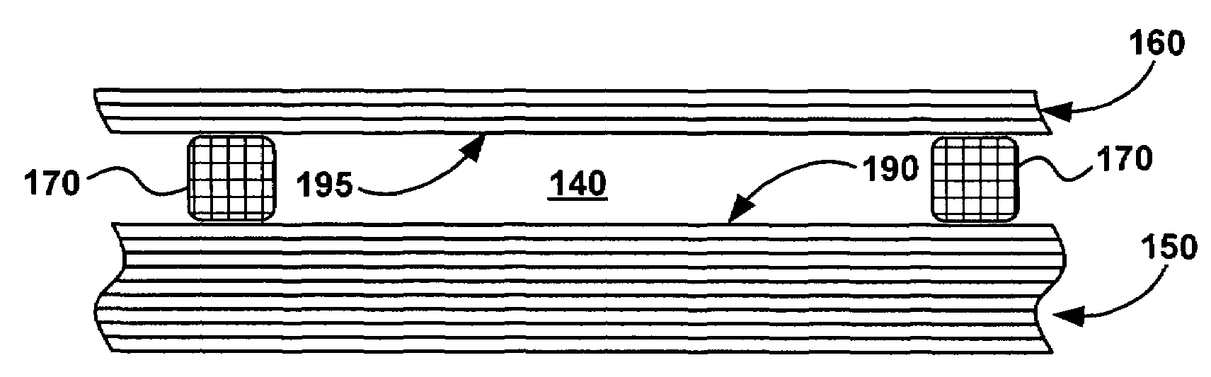
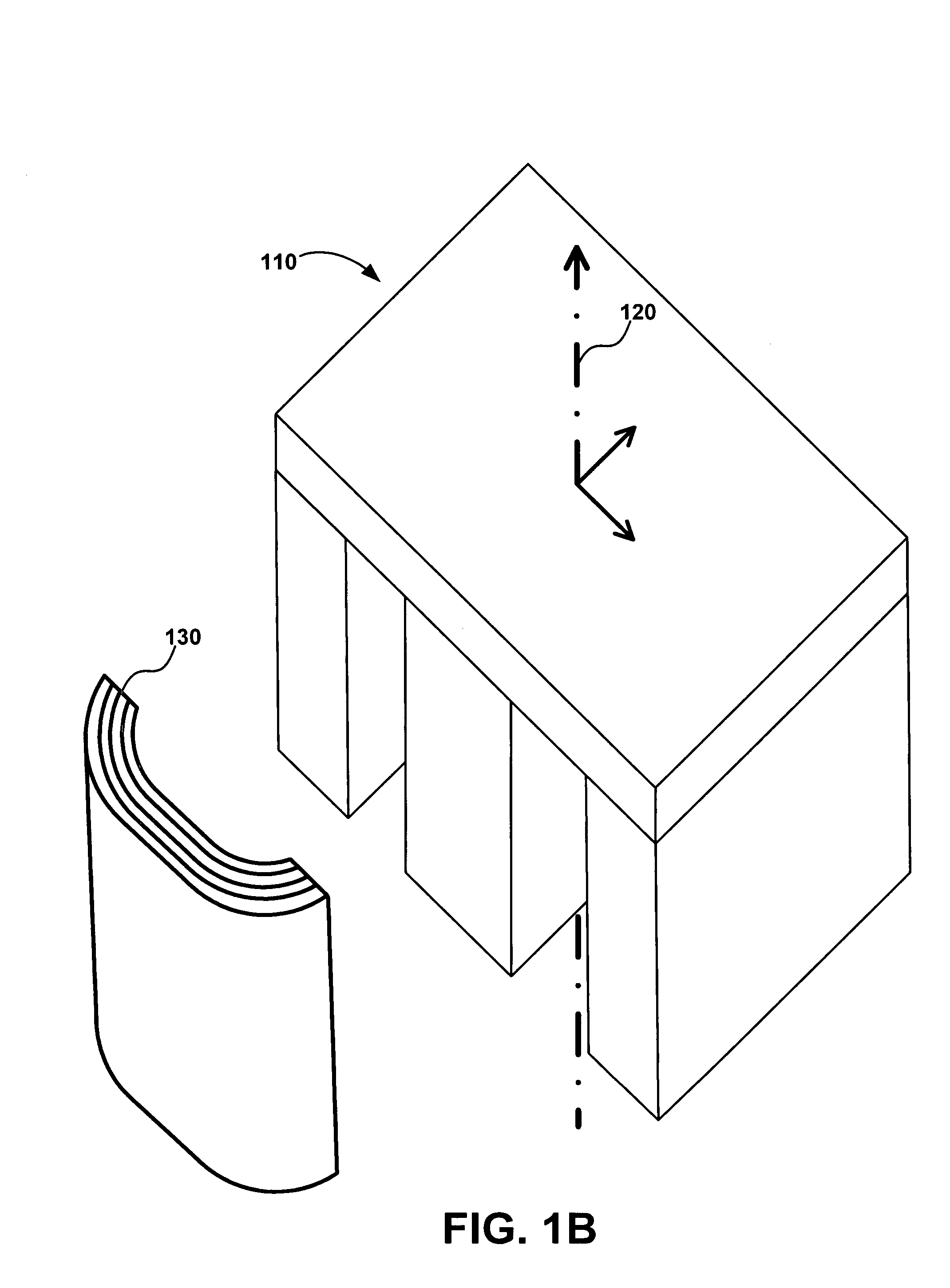
[0048]Referring toFIG. 1B, the inductor 100 includes a ferromagnetic inductor core 110 with a central axis 120. Inductor windings 130 including flat, flexible sheets, foils, or wire are wrapped in a well-known manner around the inductor core 110. In alternative embodiments, the inductor windings 130 have different configurations than illustrated (e.g., wire, foil). Alternately, inductor 100 may be similarly created in a modular fashion by winding the windings 130 around a bob...


PUM

PropertyMeasurementUnit
DC currentsaaaaaaaaaa
outer perimeteraaaaaaaaaa
perimeteraaaaaaaaaa

Abstract

A cooled high-power vehicle inductor includes an inductor core including a central axis; a first series of inductor windings around the central axis of the cooled high-power vehicle inductor, the first series of inductor windings having an outer perimeter; a second series of inductor windings around the central axis of the cooled high-power vehicle inductor, the second series of inductor windings having an inner perimeter that is substantially outside the outer perimeter of the first series of inductor windings, wherein the second series of inductor windings is electrically coupled to the first series of inductor windings; and a first heat transfer insert that is disposed between the outer perimeter of the first series of inductor windings and the inner perimeter of the second series of inductor windings, the first heat transfer insert forming a heat transfer path.

Description

FIELD OF THE INVENTION[0001]The field of the invention relates to hybrid electric vehicles (HEVs) and high power hybrid drive systems. In particular, the field of the invention relates to systems and methods for cooling high-power inductors specially adapted for HEVs and electric vehicles (EVs).BACKGROUND OF THE INVENTION[0002]A hybrid electric vehicle (HEV) is a vehicle which combines a conventional propulsion system with an on-board rechargeable energy storage system to achieve better fuel economy and cleaner emissions than a conventional vehicle. In a parallel configuration (not shown), an HEV will commonly use an internal combustion engine and batteries or ultracapacitors to power electric propulsion, however the ICE will also provide mechanical power to the drive wheels.[0003]Referring to FIG. 22, in a series configuration, an HEV drive system 2200 will commonly use an energy source such as an internal combustion engine (ICE) 2210 and a pack 2220 of batteries or ultracapacitors...

Claims


Application Information

Patent Timeline
Patent Type & Authority Patents(United States)
IPC IPC(8): H01F27/08
CPCH01F27/10H01F27/22H01F27/2876Y10T29/49071H01F27/322
Inventor WERNICKI, PAUL F.
Owner SHEPPARD MULLIN RICHTER & HAMPTON
Why Eureka
Try Eureka