Monitoring and control device and bridge module therefor

a technology of monitoring and control device and bridge module, which is applied in the direction of electric vehicles, transportation and packaging, instruments, etc., can solve the problems of unsatisfactory matching of line lengths to actual required line lengths, unnecessary attenuation losses, and relatively complex top-hat rails

Inactive Publication Date: 2009-03-24
WAGO VERW GMBH
View PDF7 Cites 7 Cited by
  • Summary
  • Abstract
  • Description
  • Claims
  • Application Information

AI Technical Summary

Benefits of technology

[0013]The bridge module preferably has a monitoring unit for detecting the interruption of the system bus and / or for detecting disconnection of the supply voltage if a system module is removed from the sequence of system modules. The system bus and / or the voltage supply is then provided for the sequence of system modules adjoining the bridge module with as little delay as possible with the aid of the monitoring unit. This means that the voltage supply and the system bus are not provided permanently by the bridge module, but only when required. The regulation of a regulated switched mode power supply of a voltage supply module is therefore prevented from being disrupted, and correct termination of the system bus is ensured. In order to provide a redundant system bus, the bridge module preferably has a terminating resistor, which is connected in the correct state. Only if an interruption of the system bus has been detected is the terminating resistor replaced by the system bus, which is connected to the bridge module via a floating line.
[0016]It is likewise advantageous if a bridge module has connection terminals, which are accessible from the outside, for a separate system bus line which can be connected to another system module of the monitoring / control device. In this case, the bridge module for providing a redundant voltage supply does not need to be identical to the bridge module for providing a redundant system bus. A dedicated bridge module can be provided for each purpose. However, it is advantageous to integrate the two functions in one bridge module. The connection terminals for the system bus are preferably provided for connection to connection terminals, which are accessible from the outside, of a field bus coupling module. The field bus coupling module is in this case modified such that connection terminals, which are accessible from the outside, are provided there for the system bus.
[0017]It is also advantageous if a bridge module has both connection terminals for the redundant system bus and connection terminals for a supply voltage. The system bus and the supply voltage are therefore provided by floating lines, which are plugged into the connection terminals of the bridge module. The monitoring unit can easily be designed such that a removal of a system module is detected using a dip in the supply voltage and, subsequently, countermeasures can be introduced immediately by connecting the redundant supply voltage to the terminal contacts of the bridge module and connecting the system bus to the corresponding terminal contacts of the bridge module.

Problems solved by technology

However, this has the disadvantage that the top-hat rails are relatively complex, and the line lengths are not matched optimally to the actually required line lengths.
This may result in unnecessary attenuation losses.
In addition, the system bus lines and voltage supply lines are accessible from the outside and are subject to a potential risk of interference.
In the implementation of the system bus and / or the voltage supply line using the first design with connection terminals at the system modules for the further connection of the system bus or the voltage supply line to an adjacent system module, there is the problem that the system bus and the voltage supply line is interrupted by a system module in a sequence of system modules being removed.

Method used


Image

  • Monitoring and control device and bridge module therefor
  • Monitoring and control device and bridge module therefor
  • Monitoring and control device and bridge module therefor

Examples


Embodiment Construction

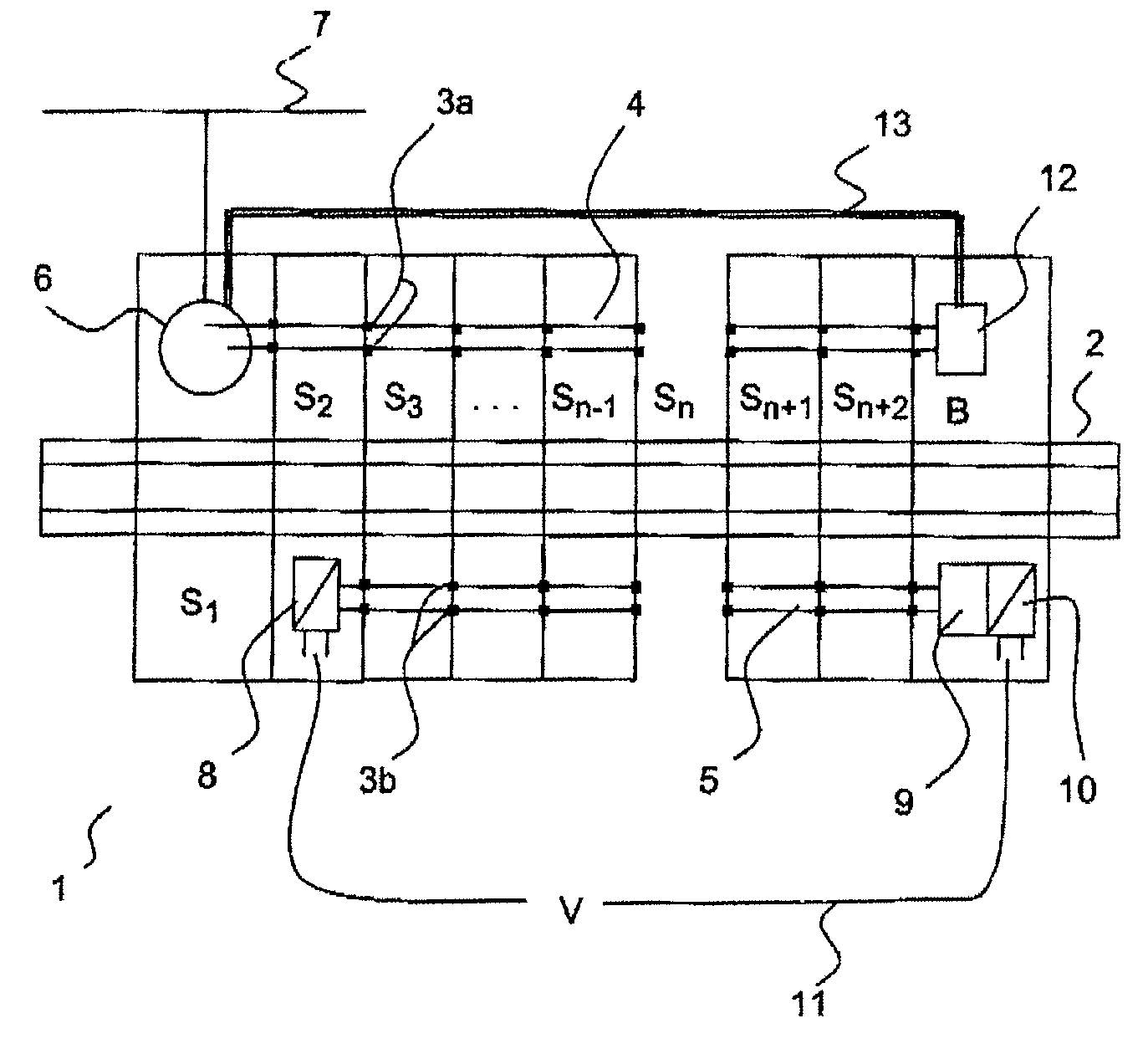
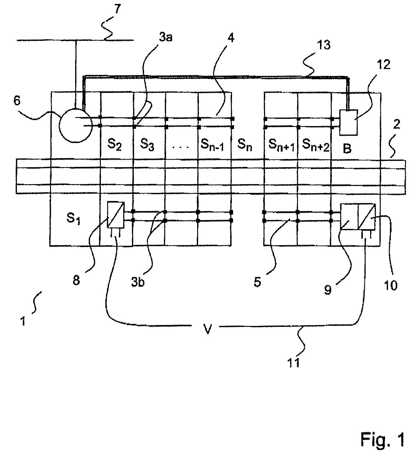
[0021]FIG. 1 shows a block diagram of a monitoring and / or control device 1, in which an assembly of system modules Si, where i=1 to N, is plugged onto a top-hat rail 2. The system modules Si are arranged adjacent to one another and have terminal contacts 3a for a system bus 4 and terminal contacts 3b for a voltage supply line 5. Depending on the design, it is also possible for only either the system bus 4 or the voltage supply line 5 to be realized with the aid of the terminal contacts 3a, 3b. In each case one terminal contact 3 on the left-hand side of a system module Si is connected to an associated terminal contact 3 on the right-hand side of the housing of the system module Si. The terminal contacts 3 are designed such that, when a system module Si is plugged on, the terminal contact 3 is electrically connected to a corresponding terminal contact 3 of the adjacent system module Si. In this manner, a system bus 4 or a voltage supply line 5 is formed in a simple manner by system m...


PUM


Abstract

Disclosed is a monitoring and / or control device (1) having an assembly of system modules (Si) in the form of field bus coupler modules, supply modules and / or input / output modules, which are arranged adjacent to one another and have terminal contacts in order to connect a system bus (4) and / or a voltage supply terminal of a system module (Si) to the subsequent system module (Si+1). At the end of the assembly of system modules (Si), a bridge module (B) is provided opposite a field bus coupler (S1) for coupling the system bus (4) to a field bus (7) and / or opposite a voltage supply module (S2) for feeding a supply voltage for the connected system modules (Si) for the redundant voltage supply of the system modules (Si) adjoining the bridge module (B) and / or for providing the system bus (4) for the system modules (Si) adjoining the bridge module (B) if a system module (Si) is removed from the sequence of system modules (Si).

Description

BACKGROUND OF THE INVENTION[0001]1. Field of the Invention[0002]The invention relates to a monitoring and / or control device having an assembly of system modules in the form of field bus coupler modules, supply modules and / or input / output modules, which are arranged adjacent to one another and have terminal contacts in order to connect a system bus and / or a voltage supply terminal of a system module to the subsequent system module.[0003]2. Description of the Related Art[0004]Such monitoring and / or control devices are known, for example, for programmable logic controllers (PLCs) or process monitoring systems and are described in DE 44 02 002 A1. System modules which each have a dedicated housing having electrical connection terminals which are accessible from the outside are plugged onto a common top-hat rail. The system modules are arranged adjacent to one another on the top-hat rail, associated electrical contact terminals of mutually adjoining system modules being connected to one ...

Claims


Application Information

Patent Timeline
Patent Type & Authority Patents(United States)
IPC IPC(8): H02M1/00
CPCH02J7/00G06F13/4027
Inventor ALBERS, THOMAS
Owner WAGO VERW GMBH
Why Eureka
Try Eureka