
Acoustic sound routing in vehicles

a technology for acoustic sound and vehicles, applied in vehicle arrangements, transportation and packaging, instruments, etc., can solve the problems of reducing accident safety, unable to adjust the volume for each seat, and commercial appliances today only allow coarse balancing of volume, so as to reduce resonance effects, reduce the effect of resonan

Inactive Publication Date: 2009-03-24
DAIMLER AG
View PDF4 Cites 24 Cited by
  • Summary
  • Abstract
  • Description
  • Claims
  • Application Information

AI Technical Summary

Benefits of technology

This solution ensures optimal acoustic impedance matching, reduces resonance effects, and enhances safety by eliminating large hard components, allowing for improved audio distribution and design flexibility in vehicles.

Problems solved by technology

Normally, however, commercial appliances today allow only coarse balancing of the volume between “right” and “left” and between “front” and “back”.
Finer volume adjustment for each seat is not possible.
A drawback of these arrangements in which the acoustic system's loudspeaker is directly in the headrest is the reduced accident safety, in particular, since relatively large hard objects are integrated in the otherwise soft headrest and could result in head injuries.
In addition, integrating relatively large-volume loudspeakers greatly restricts the visual design options for the headrest.

Method used


Image

  • Acoustic sound routing in vehicles
  • Acoustic sound routing in vehicles
  • Acoustic sound routing in vehicles

Examples


Embodiment Construction

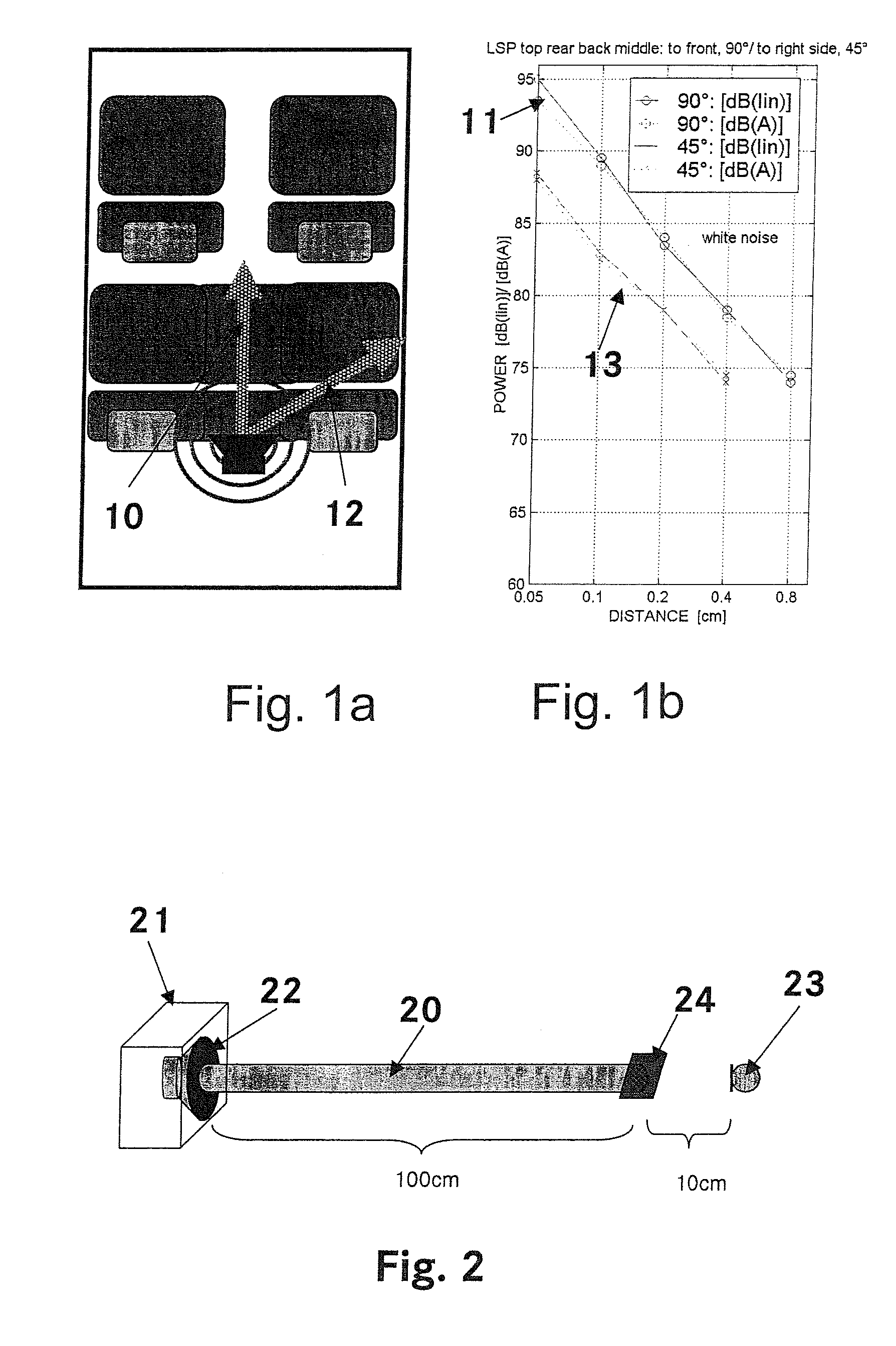
[0023]FIG. 1a) schematically shows the interior of a motor vehicle with two individual seats, driver and front passenger seats, and a bench seat in the back. Within such a typical vehicle interior, the dissemination of the from a loudspeaker signal radiated in the center above the bench seat's back rest has been measured. FIG. 1b) shows the power drop in the loudspeaker signal as a function of distance. In this context, curve 11 shows the power drop in the direction 10 of the driver and of the front passenger seat and curve 13 shows the power drop in the direction 12 of the passengers on the back seat at an angle of 45° from the loudspeaker. It can clearly be seen that the sound power drops by 6 dB whenever the distance is doubled. This applies to the unweighted level and to the A weighting (the A weighting takes into account the subjective hearing sensitivity in a coarse approximation). The 6 dB value is the correct value if we are in the direct sound field of the sources. This con...


PUM


Abstract

To ensure the same high quality of acoustic radiation from audio systems on each seat of current vehicles, an acoustic device is provided for generating audio signals, which allows sound sources to be integrated into the area located near the headrest of a vehicle seat such that the volume can be regulated in an individual manner without unduly disturbing the other passengers in a vehicle. The headrest does not comprise any loudspeakers, thus is safe regarding accident protection. The acoustic near field at the headrest is generated by means of a sound channel. The loudspeaker is disposed inside the backrest or under the seat, for example, while the sound channel terminates in the headrest. Tuned pipes, the end of which is adjusted to the acoustic impedance of the clearance zone, are used as a sound channel.

Description

CROSS REFERENCE TO RELATED APPLICATION[0001]This application is a national stage of PCT / EP2003 / 012989 filed Nov. 20, 2003 and based upon DE 102 55 794.2 filed Nov. 28, 2002 under the International Convention.BACKGROUND OF THE INVENTION[0002]1. Field of the Invention[0003]The invention relates to an acoustic apparatus for producing audio signals.[0004]2. Related Art of the Invention[0005]Audio diffusion in vehicles today is intended to ensure the same level of quality in every seat. The aim is for all occupants to hear virtually the same audio signal at the same quality and at the same volume; in complex systems, this includes with a stereo or surround effect. Normally, however, commercial appliances today allow only coarse balancing of the volume between “right” and “left” and between “front” and “back”. Finer volume adjustment for each seat is not possible. Techniques are known which are aimed at separating the audio output so that people who are physically next to one another can ...

Claims


Application Information

Patent Timeline
Patent Type & Authority Patents(United States)
IPC IPC(8): H04R1/02H04R1/28H04R1/30
CPCH04R1/023G01N2291/02491H04R2499/13B60N2/879
Inventor HOFMANN, MARCUSLINHARD, KLAUS
Owner DAIMLER AG
Learn More