Superconducting device having cryosystem and superconducting switch

a superconducting switch and superconducting device technology, applied in superconducting magnets/coils, lighting and heating apparatuses, magnetic bodies, etc., can solve problems such as the constant heating of the switching path in the activated/resistive sta

Active Publication Date: 2009-03-31
SIEMENS HEALTHCARE GMBH
View PDF20 Cites 12 Cited by
  • Summary
  • Abstract
  • Description
  • Claims
  • Application Information

AI Technical Summary

Benefits of technology

[0010]In the cryosystem of the superconducting device according to the invention, the thermal coupling of the superconducting switch thus takes place via that part of the cryogenic medium which cools the superconductors of the superconducting appliance via that part of the cryogenic medium which is located in the pipeline. On the one hand, this makes it possible to provide cooling with very good coupling and with little dissipated power in the switch, with this coupling being comparable to bath cooling; on the other hand, refrigeration power which can be transferred to the switch can be effectively limited by the choice of the cross section of the pipeline in the area of its constriction, by reducing the heat flow from the activated switching path, which is now resistive, into the coolant area that is connected to the pipeline. This makes it possible to keep the switch in the normally conductive state with relatively low dissipated losses U2 / R (where U=the voltage that is dropped across the switching path that has become resistive, and R=its resistance), which may be considerably below the watts area of known thermally switching switches. Any excessive power loss which may occur in the switch then leads to continuous heating of the switching path in the activated / resistive state. This advantageously makes it possible to ensure a safe switching state and, in the process, to limit the required refrigeration power of the cryosystem and of its refrigeration installation.
[0011]Desired limiting of the heatflow into the cryogenic medium in the coolant area can in general be achieved with the cross-sectional constriction having a cross-sectional area between 0.5 mm2 and 100 mm2, preferably between 7 mm2 and 30 mm2. This on the one hand makes it possible to ensure sufficiently good cooling of the switching path without, on the other hand, too much heat entering the coolant line system.
[0012]The cross-sectional constriction should preferably be located in a part of the pipeline facing the superconducting switch, in order to prevent heat from being introduced into larger parts of the cryogenic medium.
[0013]The coolant area may advantageously be part of a coolant line system with coolant paths on or through the at least one superconducting appliance. This makes it possible to limit the required amount of cryogenic medium.
[0016]The at least one superconducting appliance and the superconducting switch may be arranged in a common vacuum area. Superconducting connecting conductors can then advantageously run through the vacuum area, between the switching path and the superconductors of the appliances, without particularly complex cooling measures.

Problems solved by technology

Any excessive power loss which may occur in the switch then leads to continuous heating of the switching path in the activated / resistive state.

Method used


Image

  • Superconducting device having cryosystem and superconducting switch
  • Superconducting device having cryosystem and superconducting switch
  • Superconducting device having cryosystem and superconducting switch

Examples


Embodiment Construction

[0024]Reference will now be made in detail to the preferred embodiments of the present invention, examples of which are illustrated in the accompanying drawings, wherein like reference numerals refer to like elements throughout.

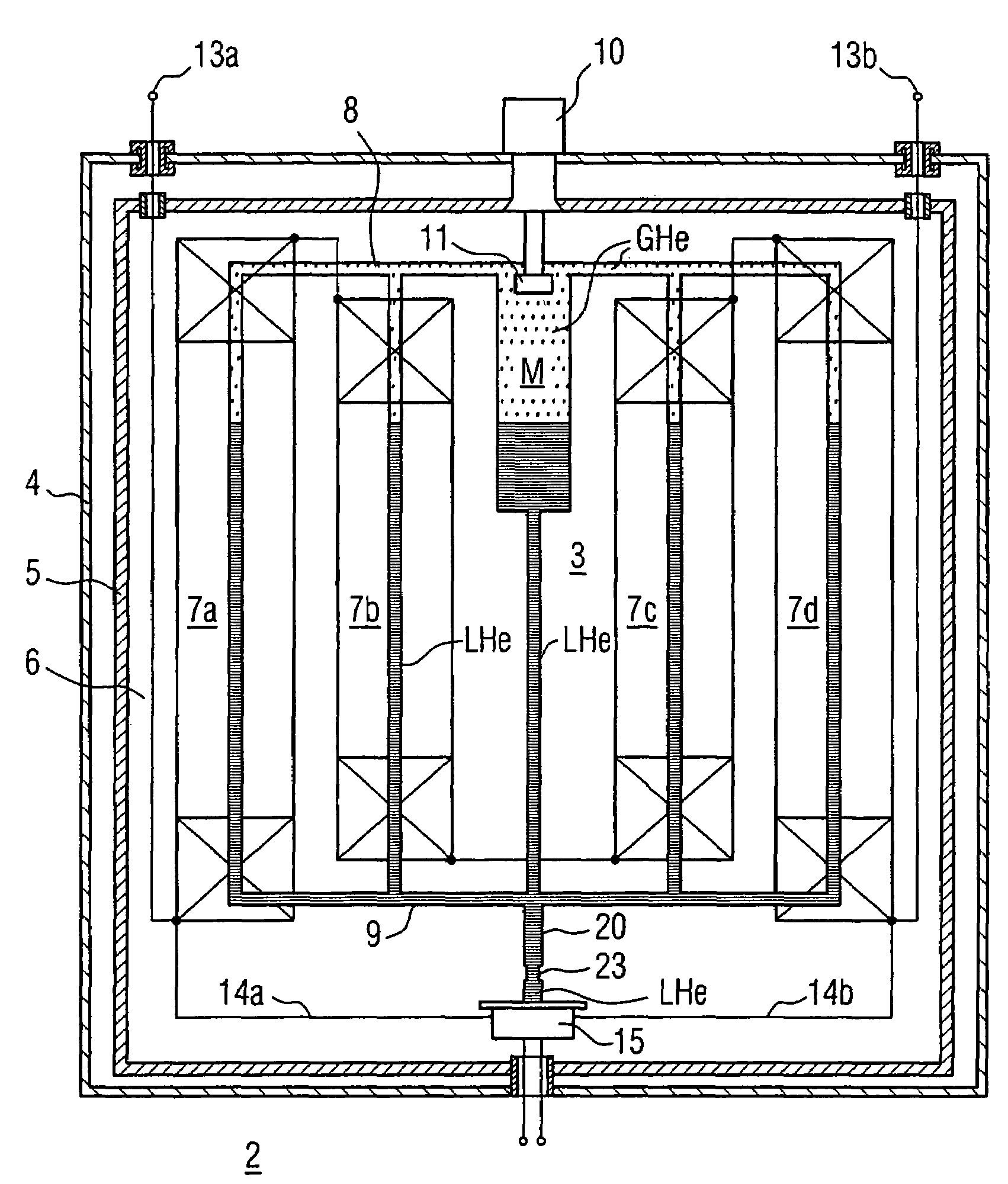
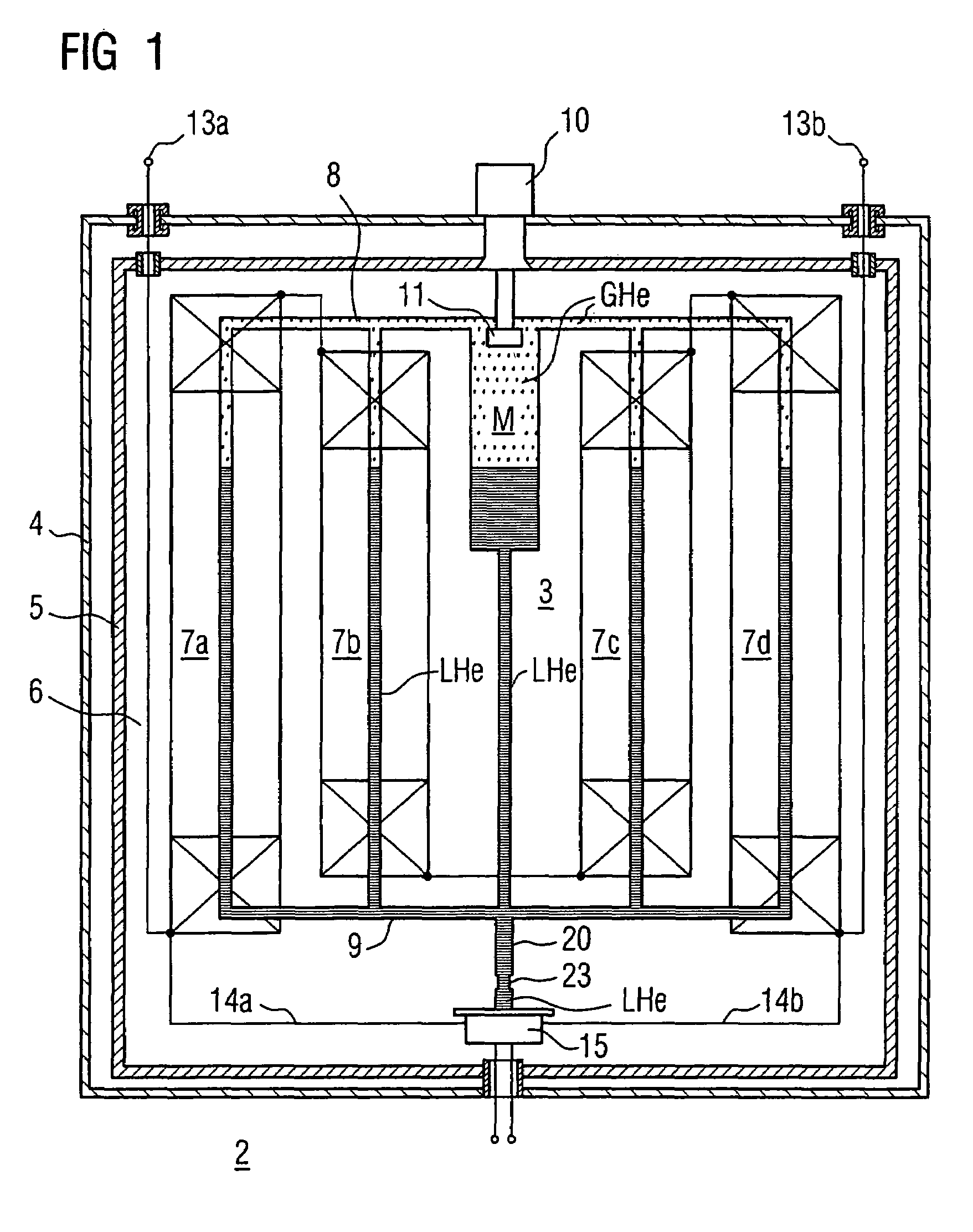
[0025]The cryosystem designed according to the invention may be provided per se for any desired superconducting devices which require at least one superconducting switch for their at least one superconducting appliance. Superconducting appliances or apparatuses may, for example, be a magnet, a machine or a transformer; alternatively, it may be a superconducting cable. The superconducting appliance is preferably an MRI magnet or a corresponding magnet system, which can be short-circuited by at least one superconducting continuous-current switch for the operating state. The following text is based on the assumption of an exemplary embodiment such as this.

[0026]The superconducting device which is annotated generally by2 in FIG. 1 has a cryosystem 3 with a cryost...


PUM

PropertyMeasurementUnit
cross-sectional areaaaaaaaaaaa

Abstract

A superconducting device has a cryosystem to whose cryogenic medium a superconducting appliance and a superconducting switching path (which is electrically connected to it and can be activated thermally by means of a heater) of a superconducting switch are thermally coupled. A pipeline, to whose end the superconducting switching path is thermally coupled, is connected to a coolant area of at least one superconducting appliance. To ensure reliable heating of the switching path when the heater is activated, the pipeline has a cross-sectional constriction which impedes the heat exchange with the coolant area.

Description

CROSS REFERENCE TO RELATED APPLICATIONS[0001]This application is based on and hereby claims priority to German Patent Application No. 10 2004 057 204.6 filed on Nov. 26, 2004, the contents of which are hereby incorporated by reference.BACKGROUND OF THE INVENTION[0002]1. Field of the Invention[0003]The invention relates to a superconducting device having a cryosystem with a cryogenic medium cooled by a refrigeration installation. The superconductors of at least one superconducting appliance and the superconducting switching path, which is electrically connected to these superconductors, of a superconducting switch are thermally coupled. The superconducting switching path has associated heating means for controlled changing of the superconducting material of the switching path to the normally conductive state.[0004]2. Description of the Related Art[0005]EP 0 074 030 A2 discloses a corresponding superconducting device having a cryosystem of the relevant type.[0006]In the case of superc...

Claims


Application Information

Patent Timeline
Patent Type & Authority Patents(United States)
IPC IPC(8): F25B19/00F17C3/10H01F1/00H01F6/06H01L39/00
CPCH01L39/20F17C2270/0527H10N60/355H01F6/04
Inventor VAN HASSELT, PETER
Owner SIEMENS HEALTHCARE GMBH
Why Eureka
Try Eureka