
Suspended steam boiler

a steam boiler and suspension technology, applied in steam superheaters, steam boiler components, water-tube boilers, etc., can solve the problems of increasing weight, affecting the construction efficiency of the steam boiler, and involving a substantial construction and welding expenditure, so as to reduce the construction expenditure for the suspension of the lower portion of the steam boiler

Inactive Publication Date: 2009-03-31
MITSUBISHI POWER EURO LTD
View PDF20 Cites 3 Cited by
  • Summary
  • Abstract
  • Description
  • Claims
  • Application Information

AI Technical Summary

Benefits of technology

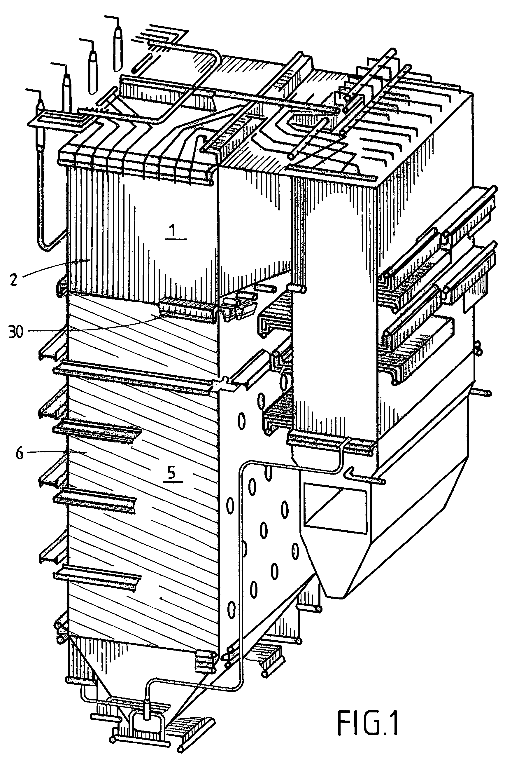
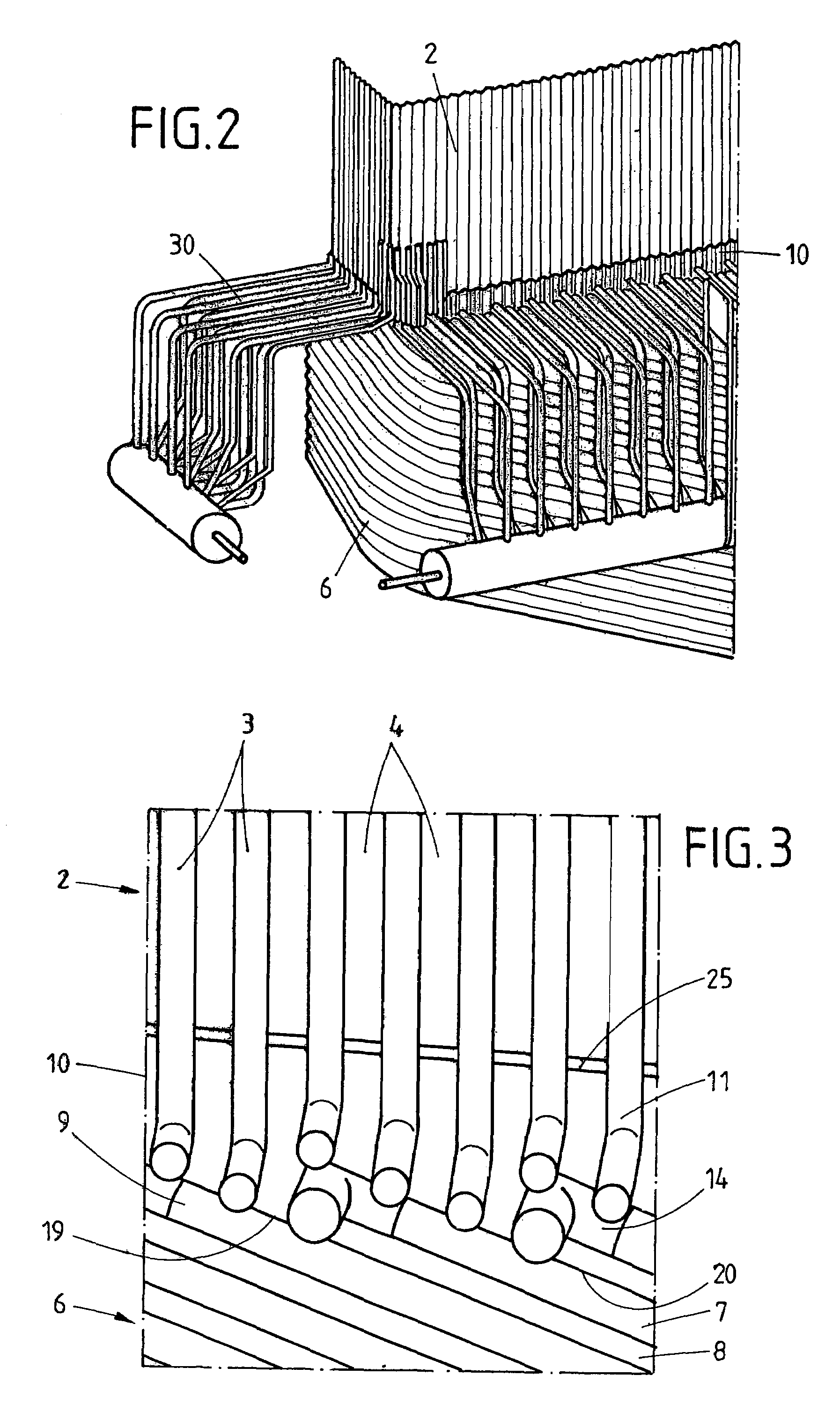
[0013]Outside of the vertical limbs of the vertical tube bends, a thermal expansion joint is formed between the coupling strip and the vertical webs of the vertical tube wall. Between the steam boiler upper portion and the steam boiler lower portion an external manifold system is formed which is connected to the respective connecting limbs of the vertical tube bends and the inclined tube bends. Due to the incorporation of the vertical limbs of the vertical tube bends and the inclined limbs of the inclined tube bends into the coupling strip by which the inclined tube wall is connected at the transition to the vertical tube walls, the manifold system is completely relieved of the weight of the steam boiler lower portion.
[0015]Due to the omission of additional tensile and support elements, by which, according to the state of the art, the weight of the steam boiler lower portion is transmitted in addition to the load transfer along the vertical tubes into the vertical tube wall, an appreciable reduction of the overall weight of the steam boiler is attained because all such tensile and support elements including the welding-on members required for fastening to the inclined tube wall and the vertical tube wall, are dispensed with. Without separate tensile and support elements, moreover, the assembly of the complete inclined tube region of the steam boiler is simple and can be performed solely with minor welding expenditure, and damage to the inclined tube wall due to uneven heating in the region of the burner chamber, is dispensed with. In addition, the fluctuating loading of the membrane tube wall is eliminated which, otherwise, would occur with each loading change of the steam boiler from the lagging behind of the tensile and support elements in relation to the inclined tube wall, and there exists substantial freedom as regards the speed with which load changes are permissible during starting up and closing down the steam boiler.

Problems solved by technology

Moreover, the application of the numerous connections of the tensile elements to the inclined tube wall involves an appreciable construction and welding expenditure.
However, this known proposal itself involves a substantial constructional expenditure combined with an increased weight due to the support element which must be absorbed by the vertical tube wall.

Method used


Image

  • Suspended steam boiler
  • Suspended steam boiler
  • Suspended steam boiler

Examples


example

Steam Boiler Upper Portion:

[0033]Vertical tubes having an outer diameter Da=38 mm and a wall thickness not less than 5 mm, spacing of the vertical tubes not less than 58 mm, web thickness of the vertical webs s=6 or 8 mm respectively. Depending on the thermal load in the combustion chamber, internal pressure and weight, the wall thickness of the tube may be, for example, 5,6 mm, 6,3 mm or 7,1 mm.

Steam Boiler Lower Portion:[0034]Inclined tubes having an outer diameter Da=42,4 or 44,5 respectively and a wall thickness not less than 5,6 mm, spacing of the inclined tubes not less than 58 mm, web thickness of the inclined webs s=6 or 8 mm respectively. Depending on the thermal load in the combustion chamber, the internal pressure and the weight, the wall thickness may, for example, be 5,6 mm, 6,3 mm or 7,1 mm.

[0035]The material of manufacture according to EN 10216, DIN or VDTÜV-material sheet of the inclined tube wall, depending on thermal load in the combustion chamber, internal pressur...


PUM


Abstract

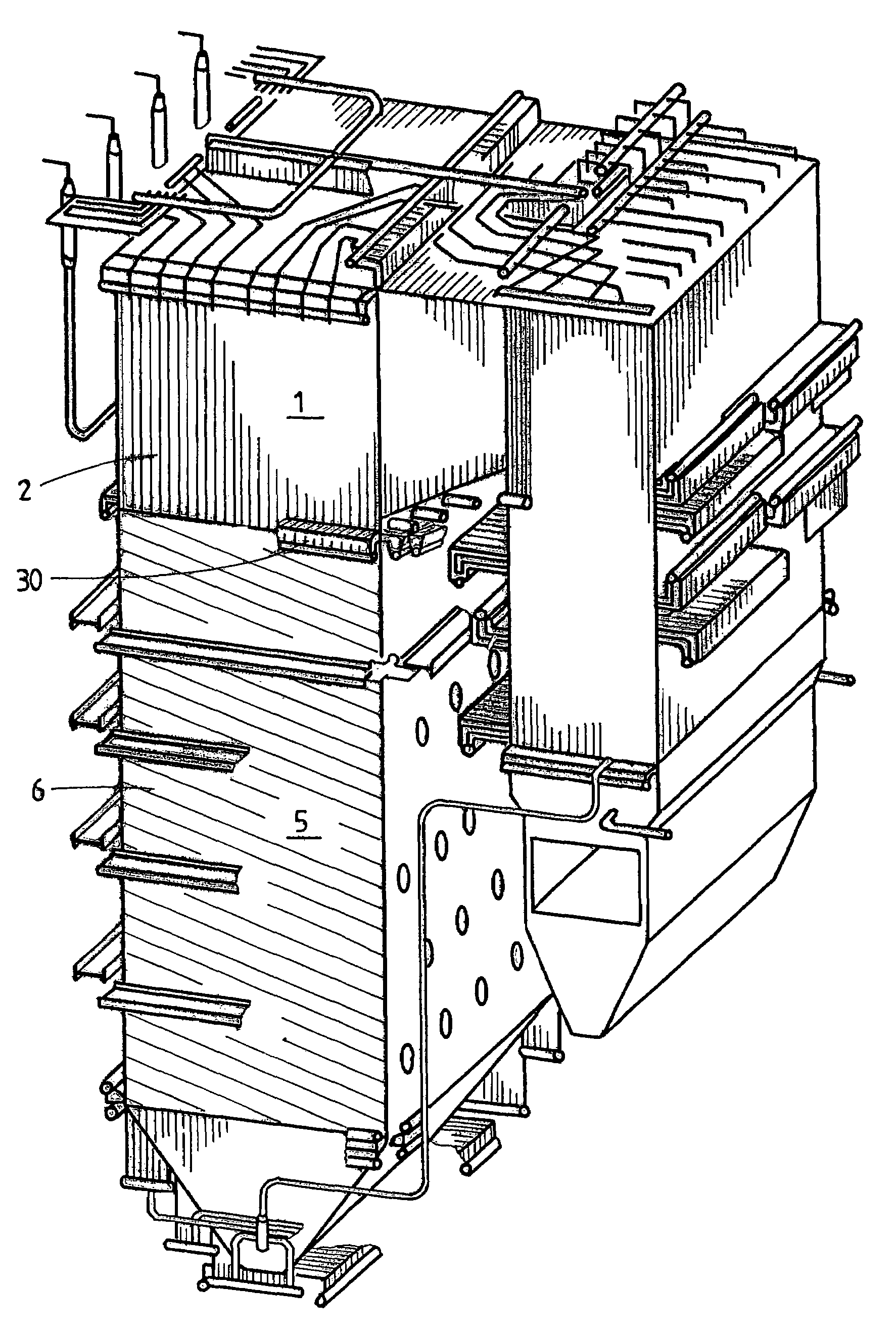
Suspended steam boiler, in which the steam boiler lower portion (5), having inclined tubes, is suspended from the steam boiler upper portion (1), having vertical tubes exclusively from the vertical tubes of the latter without additional external tensile or support elements. (FIG.1)

Description

CROSS REFERENCE TO RELATED APPLICATIONS[0001]Applicants claim priority under 35 U.S.C. §119 of German Application No. 10 2006 005 208.0 filed Feb. 2, 2006.BACKGROUND OF THE INVENTION [0002]1. Field of the Invention[0003]The invention relates to a suspended steam boiler including a steam boiler upper part, comprising a vertical tube wall, composed of vertical tubes and vertical web formed there between and a steam lower portion suspended from the vertical tube wall including an inclined tube wall composed of inclined tubes and inclined webs formed there between.[0004]2. Description of the Related Art[0005]The walls of larger sized steam boilers operating according to the forced once-through principle or forced circulation principle are nowadays designed as diaphragm tube walls composed of tube and web constructions. In order for the boilers to be able to expand freely, they are suspended in a boiler scaffolding. For that purpose, the boiler scaffolding includes a boiler scaffolding t...

Claims


Application Information

Patent Timeline
IPC IPC(8): F22B37/10
CPCF22B21/00F22B29/065F22B37/244F22B37/645F22G7/145
Inventor BECKER, MARTINLAI, VU-TAM
Owner MITSUBISHI POWER EURO LTD
Learn More