Brake system for railway vehicles

a technology for railway vehicles and brake systems, applied in brake systems, brake action initiation, transportation and packaging, etc., can solve the problems of limited freedom of construction, heavy weight of pneumatic installations, and expenditures for mounting, and achieve significant logistic simplification, reliable and simple manner, and more space for other devices.

Inactive Publication Date: 2006-01-31
KNORR BREMSE SYST FUR SCHIENENFAHRZEUGE GMBH
View PDF34 Cites 15 Cited by
  • Summary
  • Abstract
  • Description
  • Claims
  • Application Information

AI Technical Summary

Benefits of technology

[0047]The brake system according to the invention also permits a significant logistic simplification with respect to known systems, whereby it can be monitored in a more reliable and simpler manner.
[0048]Another advantage is the fact that more space for other devices is available in the vehicle body. In this case, the arrangement of the check valve and / or of the compressed-air reservoir in the bogie is relatively unproblematic because sufficient space exists here. Furthermore, the constructive possibilities for the design of the railway vehicle are expanded.
[0049]As a result of the fact that the frame or other constructive elements of the bogie are constructed at least in sections as compressed-air reservoirs, the space requirement in this area can be further reduced. In this case, the frame structure of the bogie usually produced as a welded construction is utilized in a particularly favorable manner. Thus, hollow spaces existing in the frame of the bogie, in addition to their static utilization, will have an additional use. This reduces the constructive expenditures because no additional compressed-air reservoir has to be arranged in this area. The tightness in the frame required for receiving the compressed air can be produced by conventional means by seal welding, etc.
[0050]As an alternative, the frame or other constructive elements of the bogie can also be used, at least in sections, for receiving the compressed-air reservoir. The clearances existing in the frame structure will then be advantageously utilized so that the space requirement for the compressed-air reservoir can be minimized. In this case, it is also possible to construct the frame structure as a partially or completely closed covering in one area and to insert the compressed-air reservoir. The frame can then also be used as a protective element for the compressed-air reservoir against outside influences.
[0051]When at least one other control unit is used as a monitoring unit for monitoring the triggering of an emergency braking, the advantage of an increased protection against failure is obtained. The emergency braking safety line is connected with the control unit and the fail-safe device. As a first control step, the latter monitors an output signal of the control unit in order to ensure that the control unit has correctly initiated the controlled emergency braking. Should this not be so, a switching to the pneumatic fall-back level is caused; that is, a pneumatic emergency braking of the system is caused. The use of another control unit as an additional monitoring unit or second control step helps to ensure that a switching to the pneumatic fall-back level really only has to take place in an absolute emergency. It also permits an improved checking and load-dependent controlling of a correctly initiated controlled emergency braking, so that vehicle specific data and actual operating values can be taken into account during the implementation of the emergency braking on the basis of the comparative values of the additional monitoring unit or second control step in a more differentiated manner. This results, for example, in an improved slip control and thus in an optimal utilization of the coefficient of adhesion for achieving a required stopping distance and also helps to avoid wheel flats as well as resulting repair costs. Even in the event of a failure of the first monitoring unit, a reliable emergency braking will be ensured in this manner. The additional monitoring unit or second control step can preferably be housed in another, second bogie.
[0052]According to another aspect of the present invention, a bogie for a railway vehicle is provided in which the frame is constructed at least in sections as a compressed-air reservoir. This bogie according to the invention is characterized by a functional multiple utilization. Thus it is normally used also for the bearing of the axles and for receiving the load applied by the car body. In addition, it is used as a hollow body in which compressed air can be stored. The bogie according to the invention therefore represents a particularly advantageous module for simplifying a railway vehicle. As a result, important constructive, assembly-related and financial advantages can be achieved.

Problems solved by technology

However, such a construction requires extensive pneumatic installations in the train formation and particularly between the engineer's cab and the bogies of the train vehicle.
As a result, the freedom of construction is limited when such railway vehicles are further developed because considerable space is required.
Other disadvantages are the weight of these installations and the expenditures required particularly for the mounting.
This system, which has been successful in practice, however, has the disadvantage that considerable expenditures are required for its implementation.
The known emergency system therefore requires extensive installation expenditures.
This has a disadvantageous effect on the costs for material and mounting.
It is another disadvantage that this system is relatively heavy, which has a disadvantageous effect on the energy consumption during the operation of the railway vehicle.
Furthermore, the installation expenditures and the space requirement for the electrical line are significantly lower than those for the pneumatic line in conventional systems.
However, in addition, the train engineer or a passenger can also, by way of an emergency braking device, initiate a corresponding emergency braking signal, or cause the interruption of the electric signal.
In this case, the arrangement of the check valve and / or of the compressed-air reservoir in the bogie is relatively unproblematic because sufficient space exists here.

Method used


Image

  • Brake system for railway vehicles
  • Brake system for railway vehicles
  • Brake system for railway vehicles

Examples


Embodiment Construction

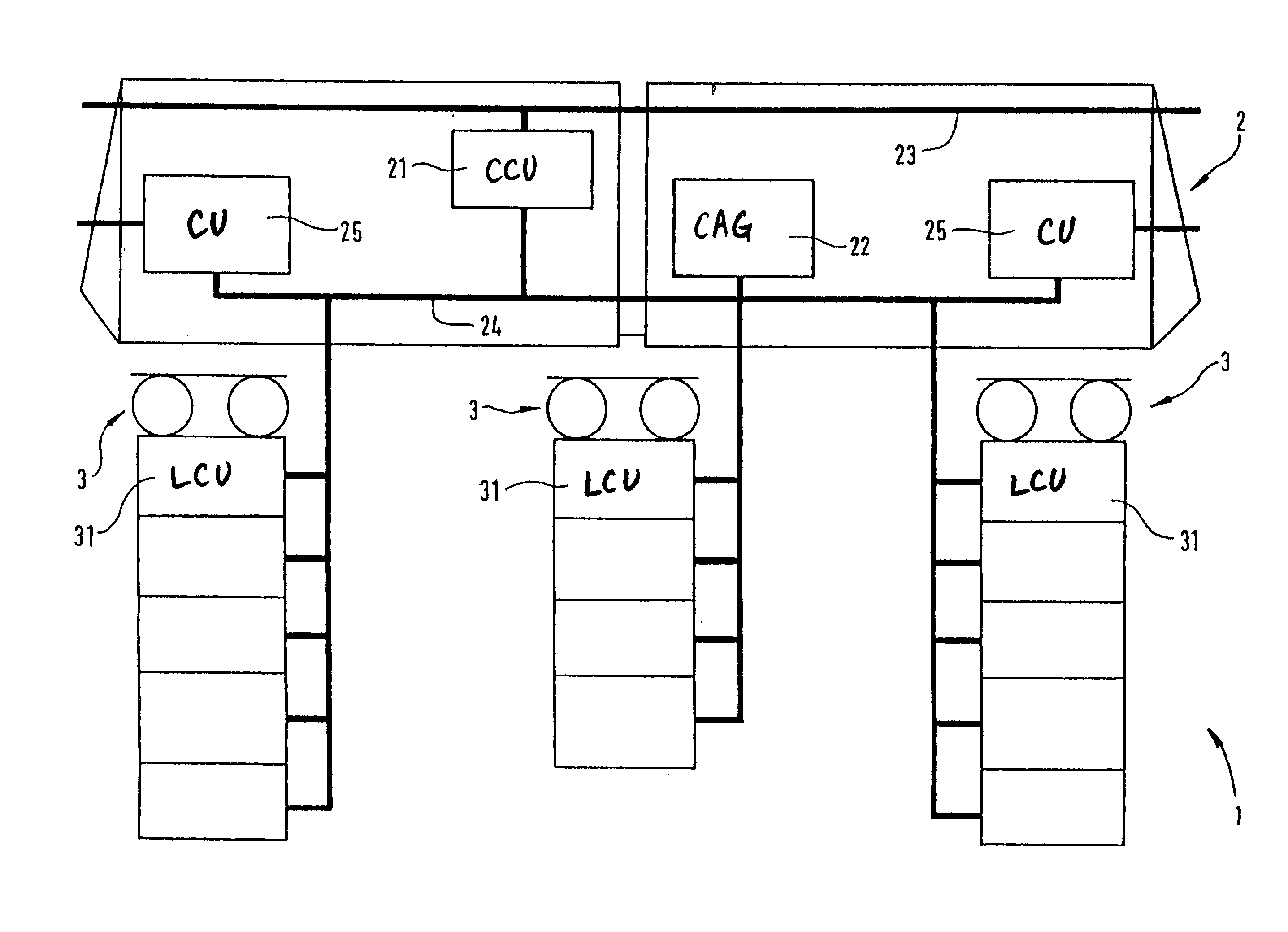
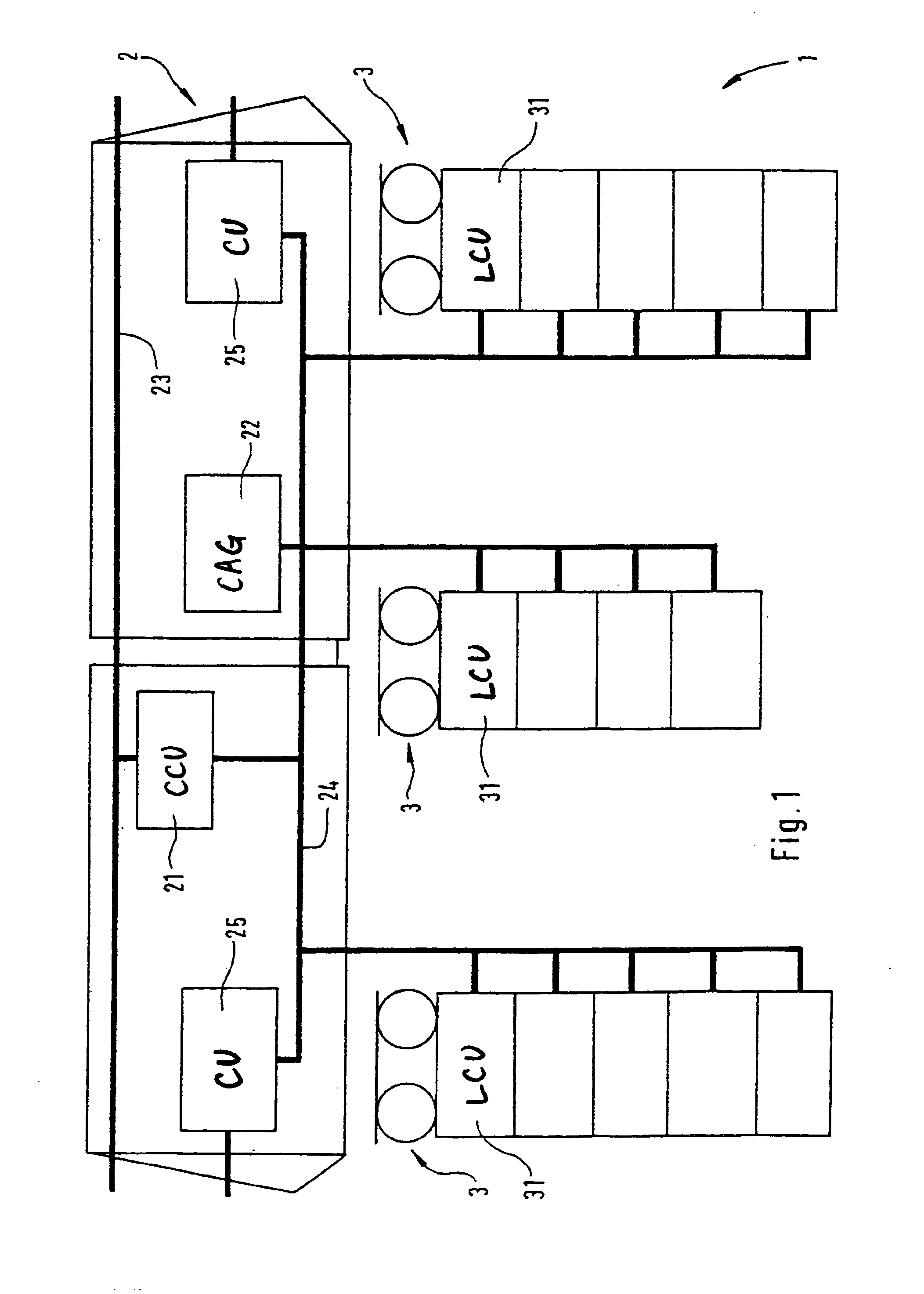
[0064]According to the schematic representation in FIG. 1, a railway vehicle 1 essentially has a vehicle body 2 and, in the present embodiment, has three bogies 3. The railway vehicle 1 is illustrated here as a traction vehicle, in which case additional driven or non-driven vehicles can be coupled for forming a train formation.

[0065]FIG. 1 illustrates the electronic controlling of the brake system of the railway vehicle 1. A central control unit 21 and a compressed-air generating device 22 are arranged in the vehicle body 2. By means of a vehicle data bus 23, the central control unit 21 receives operating data concerning the entire railway vehicle or the entire train formation. The control data for the brake system of the railway vehicle derived therefrom are transmitted by way of a braking data bus 24 to the air generating device and the local control units 31 and optionally also existing function modules in the bogies 3. By way of connection units 25, these data can also be transm...


PUM


Abstract

The invention relates to a brake system for a railway vehicle. Said brake system comprises a main air reservoir line which is fed by an air compressor unit. Every bogie truck is provided with at least one compressed-air line which is connected to the main air reservoir line either directly or via a stop valve, a non-return valve and a compressed-air reservoir. The compressed-air line feeds, for example, the service brake valves for impinging the brakes of the bogie truck or a control unit for the spring-loaded brake and/or other control units for other auxiliary components. The service brake valves and/or the spring-loaded brake and/or other auxiliary components are controlled via at least one local, electronic brake control unit.

Description

CROSS-REFERENCE[0001]This application is a continuation of U.S. application Ser. No. 09 / 830,179 filed on Aug. 2, 2001, now U.S. Pat. No. 6,669,308, which is a 371 of Application No. PCT / EP99 / 08015, filed Oct. 22, 1999.BACKGROUND AND SUMMARY OF THE INVENTION[0002]The present invention relates to a pneumatic brake system for a railway vehicle as well as to a bogie and as well as to a brake control unit.[0003]Modern brake systems for railway vehicles comprise components which are to be controlled pneumatically and / or hydraulically as well as electronically. In the standard-gauge railway domain, pneumatic systems are usually used, by means of which the braking devices of the railway vehicle as well as additional auxiliary units, such as the spring-loaded brakes, the wheel flange lubrication system, the cleaning block, the sanding device, etc., are controlled. For this purpose, the railway vehicle has a compressed-air generating device which, as a rule, directly feeds a main air reservoi...

Claims


Application Information

Patent Timeline
Patent Type & Authority Patents(United States)
IPC IPC(8): B60T13/70B60T8/18B60T8/32B60T13/66B60T17/20B60T17/22
CPCB60T8/1893B60T8/321B60T17/228B60T13/665B60T17/20B60T8/3235
Inventor AURICH, STEFANKLEEMAN, ULRICHWALDMANN, PETERFIRSCHING, PETERVOHLA, MANFRED
Owner KNORR BREMSE SYST FUR SCHIENENFAHRZEUGE GMBH
Why Eureka
Try Eureka