Container employing inner liner and vents for thermal insulation and methods of making same

a technology of inner liner and vent, which is applied in the field of containers, can solve the problems of partial vacuum formation and film not fully activating to provide maximum insulation

Inactive Publication Date: 2009-03-31
GPCP IP HLDG LLC
View PDF77 Cites 52 Cited by
  • Summary
  • Abstract
  • Description
  • Claims
  • Application Information

AI Technical Summary

Benefits of technology

[0006]The present invention provides a container suitable for providing insulation wherein the container has an inner shrink film liner. The sidewalls of the container, which can be made from paperboard or other suitable material, are vented to allow ambient air to freely flow through the sidewall of the container during activation of the shrink film. The shrink film is activated when the container is filled with liquid or other material having a temperature of from about 130° F. to up to about 212° F. The shrink film is applied using an adhesive suitable to prevent the shrink film from undergoing substantially no delamination when contacted with liquid or other material exhibiting these temperatures. When the container is filled with material having a temperature of from about 130° F. to up to about 212° F., the shrink film is activated and the container provides excellent insulation, thereby allowing the container to be held in a consumer's hand for an extended period without causing bums or excessive discomfort. Methods of making this container are also provided.

Problems solved by technology

However, in use, when the film began to shrink, a partial vacuum was formed and the film could not fully activate to provide maximum insulation effect.

Method used


Image

  • Container employing inner liner and vents for thermal insulation and methods of making same
  • Container employing inner liner and vents for thermal insulation and methods of making same
  • Container employing inner liner and vents for thermal insulation and methods of making same

Examples


example 1

Hold Times in Relation to Type of Shrink Film Used for Insulation Band

[0071]FIG. 6 shows the results of hold time tests using different types of shrink films.

[0072]Hold time was measured using a panel of about 20 men and women (generally equally divided) who held containers filled with 190° F. liquid and were asked to indicate when the container became too hot to hold comfortably. Participants were directed to not hold the container at the seam portion (which contained no insulation band). The test was stopped at 2 minutes (which was considered to conform to an infinite hold time).

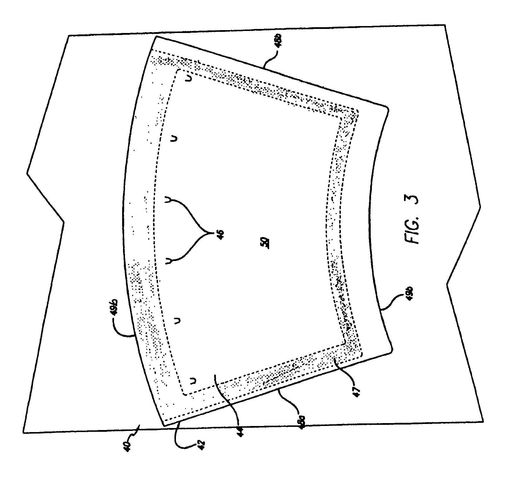
[0073]The shrink films examined were: 1. Clysar LLGT (60 gauge polyethylene film); 2. VEZT (50 gauge 3 layer polypropylene / polyethylene / polypropylene film); and 3. EZT (60 gauge 3 layer polypropylene / polyethylene / polypropylene film. These were all products of Bemis Clysar, Oshkosh, Wis. The shrink film was applied the pattern shown in FIG. 3. The adhesive used was Henkel 6B-5458M. The initial temperature o...

example 2

Cup Capacity in Relation to Type of Shrink Film Used for Insulation Band

[0075]FIG. 7 illustrates the loss of volume seen with different shrink film types. These results show that to obtain a final liquid volume of about 12 ounces, the unactivated container capacity needs to be larger to account for volume loss.


PUM


Abstract

The present invention provides a container suitable for providing insulation wherein the container has an inner shrink film liner. The sidewalls of the container, which can be made from paperboard or other suitable material, are vented to allow ambient air to freely flow through the sidewall of the container during activation of the shrink film with hot liquid or other suitable material. When the container is filled with material having a temperature of from about 130° F. to up to about 212° F., the shrink film is activated and the container provides excellent insulation, thereby allowing the container to be held in a consumer's hand for an extended period without causing burns or excessive discomfort. Methods of making this container are also provided.

Description

CROSS-REFERENCE TO RELATED APPLICATIONS[0001]This application is a continuation-in-part application of U.S. application Ser. No. 11 / 174,434, filed Jun. 30, 2005, which disclosure is incorporated herein in its entirety by this reference.FIELD OF THE INVENTION[0002]The present invention provides a container suitable for providing insulation wherein the container has an inner shrink film liner. The sidewalls of the container, which can be made from paperboard or other suitable material, are vented to allow ambient air to freely flow through the sidewall of the container during activation of the shrink film with hot liquid or other suitable material. When the container is filled with material having a temperature of from about 130° F. to up to about 212° F., the shrink film is activated and the container provides excellent insulation, thereby allowing the container to be held in a consumer's hand for an extended period without causing bums or excessive discomfort. Methods of making this...

Claims


Application Information

Patent Timeline
Patent Type & Authority Patents(United States)
IPC IPC(8): B65D81/38B31B50/62
CPCB31B7/00B31B15/00B31B17/00B65D81/3869B31B2217/0023B31B2217/0038B31B2217/0076B31B2217/062B31B2217/064B31B2217/082B31B2105/00B31B2105/0022B31B2110/10B31B2110/20B31B2120/40B31B2120/408B31B2120/50
Inventor HARTJES, TIMOTHY P.BREINING, MICHAEL A.VAN HANDEL, GERALD J.BROWN, DAVID C.MALAKHOW, WALTER
Owner GPCP IP HLDG LLC
Why Eureka
Try Eureka