Device for delivering fixed quantity of liquid

a fixed quantity, liquid technology, applied in the direction of positive displacement liquid engine, piston pump, instrument, etc., can solve the problems of prior-art devices that cannot deliver liquid in a short tact time, difficult to greatly change air pressure in a short time, and prior-art devices cannot. achieve the effect of high precision, high speed and high speed

Inactive Publication Date: 2009-03-31
MUSASHI ENG INC
View PDF26 Cites 0 Cited by
  • Summary
  • Abstract
  • Description
  • Claims
  • Application Information

AI Technical Summary

Benefits of technology

[0003]However, those prior-art devices cannot deliver the liquid in a short tact time demanded at the present, while maintaining high precision and fixed quantity.
[0004]In the die-bonding process in manufacture of semiconductors, for example, it is demanded to deliver a larger amount of liquid in a shorter time to be adapted for not only the advent of semiconductor devices having higher performance and larger sizes, but also for a higher tack required to increase productivity. On the other hand, high-precise delivery and fine coating of the liquid are demanded corresponding to requirements for high-quality products.
[0012]It is an object of the present invention to provide a delivering device, which can overcome the above-mentioned problems with techniques for delivering a fixed amount of liquid at high speed and with high precision, and can deliver the liquid at high speed and with high precision.

Problems solved by technology

However, those prior-art devices cannot deliver the liquid in a short tact time demanded at the present, while maintaining high precision and fixed quantity.
From the viewpoint of satisfying those demands, any of the above-mentioned prior-art devices has problems given below.
However, because the air pressure is highly compressible, it is very difficult to greatly change the air pressure in a short time.
Accordingly, the air type delivering device is not suitable for delivering the liquid at a high tact.

Method used


Image

  • Device for delivering fixed quantity of liquid
  • Device for delivering fixed quantity of liquid
  • Device for delivering fixed quantity of liquid

Examples


embodiment 1

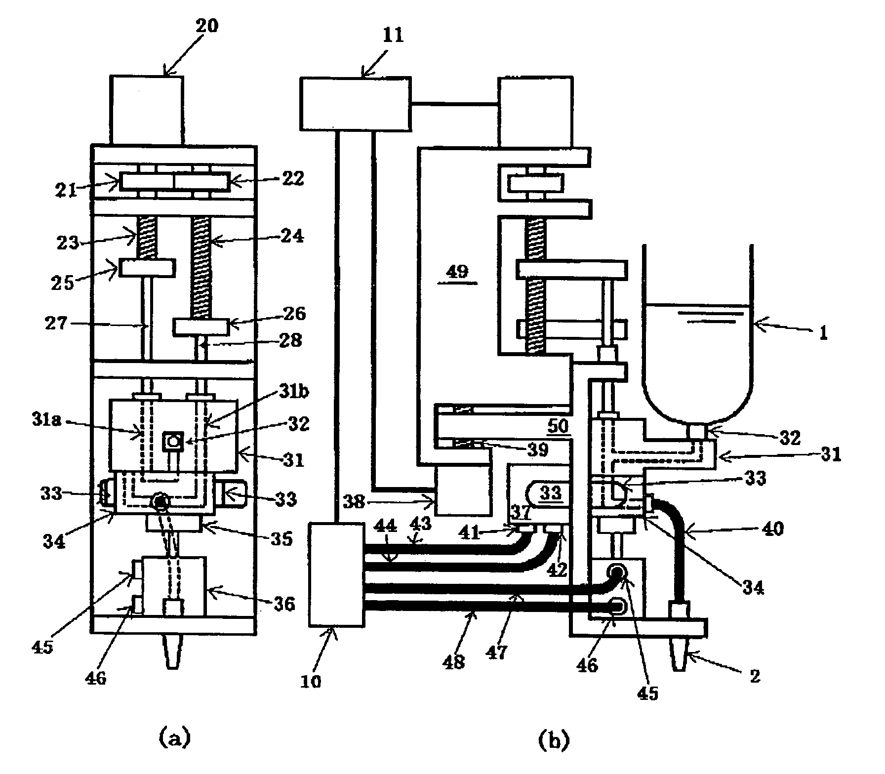
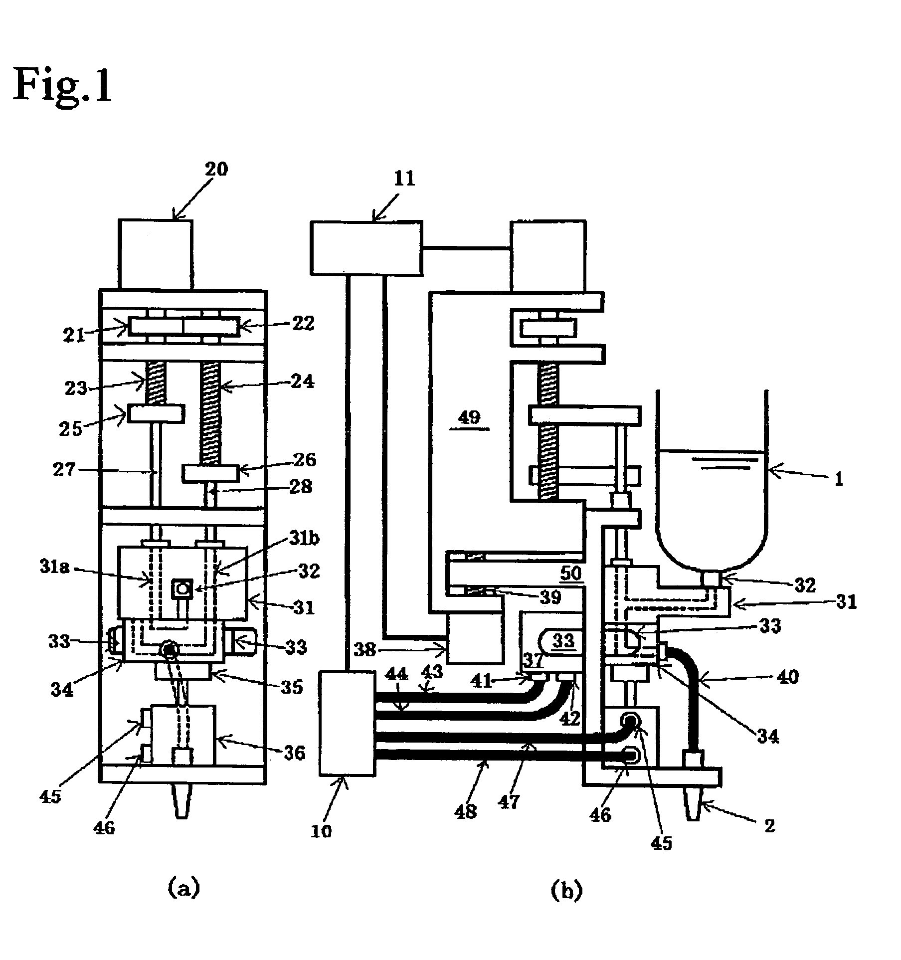
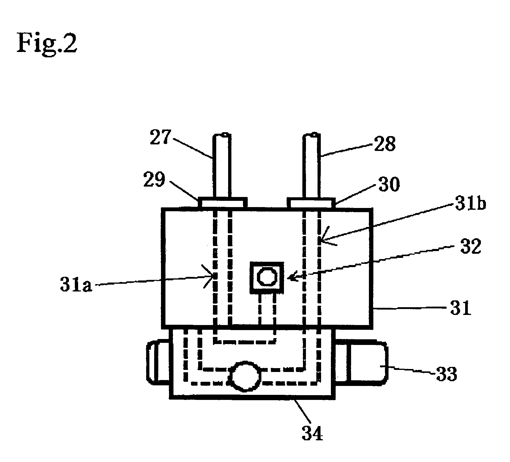
[0049]One embodiment of the present invention will be described with reference to FIGS. 1 and 2.

[0050]In the Figures, numeral 31 denotes a cylinder block which is made of a block-shaped metal material and has cylindrical penetration holes bored in it to form a plunger chamber A 31a and a plunger chamber B 31b. A plunger rod A 27 and a plunger rod B 27 are fitted respectively in the plunger chamber A 31a and the plunger chamber B 31b to be able to advance and retreat therein. The stroke of each plunger rod is set such that a front end surface of the plunger rod in its maximum advance position is flush with one side surface of the cylinder block 31. A valve block 34 is disposed in close and slide contact with one side surface of the cylinder block 31 at which the penetration holes formed in the cylinder block 31 are opened. The valve block 34 is also held in pressure contact with the cylinder block 31 by a pushing member 35 so that a liquid is prevented from leaking through the interf...

embodiment 2

[0075]In above Embodiment 1, two plunger rods are driven by one motor. In this embodiment, however, two motors 60, 61 are connected respectively to two plunger rods 27, 28, and an air pressure is applied to the liquid in the reservoir vessel 1 so that the liquid can be quickly filled into the plunger chambers A 31a, B 31b from the reservoir vessel 1. Main features of this embodiment are as follows.

[0076](1) The motors 60, 61 are connected respectively to two ball screws 23, 24, and therefore the two plunger rods 27, 28 can be moved independently of each other. This arrangement enables the speeds of delivery and suction to be changed as required. For a liquid requiring a longer time to suck it, therefore, the filling speed can be reduced without changing the delivery speed, and the occurrence of cavitation can be suppressed without causing an inadequate suction force to act upon the liquid.

(2) By rotating the two independent motors 60, 61 in the same direction, the relative distances...

embodiment 3

[0077]FIG. 4 illustrates Embodiment 3. While above Embodiments 1 and 2 employ, as the switching valve, a sliding switching valve, in this embodiment the switching valve block 34 has a rotary switching valve having a smooth sliding surface. More specifically, a disk-like valve body having an arc-shaped flow channel formed in its surface held in contact with the cylinder block is rotated in one direction or reciprocally. Under cooperation of the arc-shaped flow channel formed in the disk-like valve body with a hole formed in the surface of the cylinder block held in close contact with the valve block and communicating with a pump section, a hole formed in that close contact surface and communicating with the liquid reservoir vessel, and a hole formed in that close contact surface and communicating with the nozzle, the switching valve performs the switching operation between a state in which the pump section is communicated with the liquid reservoir vessel and a state in which the pump...


PUM


Abstract

To deliver a liquid at high speed and with high accuracy. A device for delivering a fixed quantity of liquid, comprising a pump section for metering the delivered liquid to provide a desired amount consisting of a plunger chamber formed in a cylinder block, and a plunger reciprocating in the plunger chamber, a valve section for switching between liquid flow channels for suction and delivery, a reservoir section for reserving liquid adapted to communicate with the pump section depending upon the position of the valve section, and a delivery section having a delivery port for delivering liquid, the device being characterized in that the pump section and the valve section are disposed connected to each other and that the maximum advance position of the plunger is defined by a plane where the front end surface of the plunger contacts the valve section and pump section. The valve section is removably disposed in the pump section. The plunger chamber is made of a cylindrical chamber fitted in a hole formed in the cylinder block. The valve section is in the form of a switching valve provided with a valve block having a first flow channel communicating with a reservoir vessel and a second flow channel communicating with the delivery section.

Description

TECHNICAL FIELD[0001]The present invention relates to a device for delivering liquids having any level of viscosity at high speed and with high precision, the liquids ranging from low-viscous materials, e.g., water and alcohol, to high-consistence fluids, such as an adhesive and pasty or creamy industrial materials.BACKGROUND ART[0002]Hitherto, various types of devices for delivering a fixed quantity of liquid have been developed; for example, (1) an air type delivering device in which compressed air is applied under regulated pressure to a liquid in a reservoir vessel for a predetermined time such that a desired amount of liquid is delivered through a delivery port at a nozzle fore end, (2) a plunger type delivering device in which a plunger is liquid-tightly disposed with respect to a liquid in a reservoir vessel and is moved to pressurize the liquid such that a desired amount of liquid is delivered through a delivery port at a nozzle fore end, and (3) a multi-plunger pump type de...

Claims


Application Information

Patent Timeline
Patent Type & Authority Patents(United States)
IPC IPC(8): G01F11/06B67D3/00F04B35/04G01F11/00B05C5/02B05C11/10F04B7/00F04B13/00G01F11/02
CPCB05C5/0225B05C11/10F04B7/0015F04B13/00G01F11/021B05C5/02F04B53/10
Inventor IKUSHIMA, KAZUMASA
Owner MUSASHI ENG INC
Why Eureka
Try Eureka