Separation system for the removal of fat, oil or grease from wastewater

a technology for wastewater and separation systems, applied in separation processes, filtration separation, multi-stage water/sewage treatment, etc., can solve the problems of organic phase suspended, blockage of wastewater piping, and inability to simply dispose of aqueous phase into sewer lines, etc., to accelerate the separation of aqueous phas

Inactive Publication Date: 2009-03-31
HILLS BLAIR H
View PDF18 Cites 7 Cited by
  • Summary
  • Abstract
  • Description
  • Claims
  • Application Information

AI Technical Summary

Benefits of technology

[0008]The present invention relates to a separation system for separating the aqueous phase from the organic phase of wastewater that is typically collected from grease traps and the like. A separator, such as a centrifugal separation device, comprises a wastewater inlet, an organic phase outlet for discharging separated organic phase material, and an aqueous phase outlet for discharging separated aqueous phase material. The system can be portable and can be mounted on a vehicle for collection and treatment at various sites. Heat can be introduced to the system to accelerate the separation of the aqueous phase from the organic phase of the wastewater.

Problems solved by technology

The aqueous phase of wastewater can be easily passed through wastewater piping and treated by wastewater treatment systems, however, if the organic phase is allowed to enter sewer lines and wastewater treatment systems, it can form blockages in the wastewater piping, primary treatment systems, publicly owned treatment works (POTWs) and leach fields.
This can cause some of the organic phase to be suspended in the wastewater as suspended solids.
In addition, the cleaning of a grease trap causes violent mixing of the organic phase and the aqueous phase thereby distributing the organic phase throughout the aqueous phase.
Accordingly, the aqueous phase cannot simply be disposed of into the sewer lines due to the organic phase contained in the emulsions dispersed throughout the aqueous phase.
Accordingly, traditional systems significantly increase the transportation costs and the energy required in typical disposal processes.

Method used


Image

  • Separation system for the removal of fat, oil or grease from wastewater
  • Separation system for the removal of fat, oil or grease from wastewater
  • Separation system for the removal of fat, oil or grease from wastewater

Examples


example

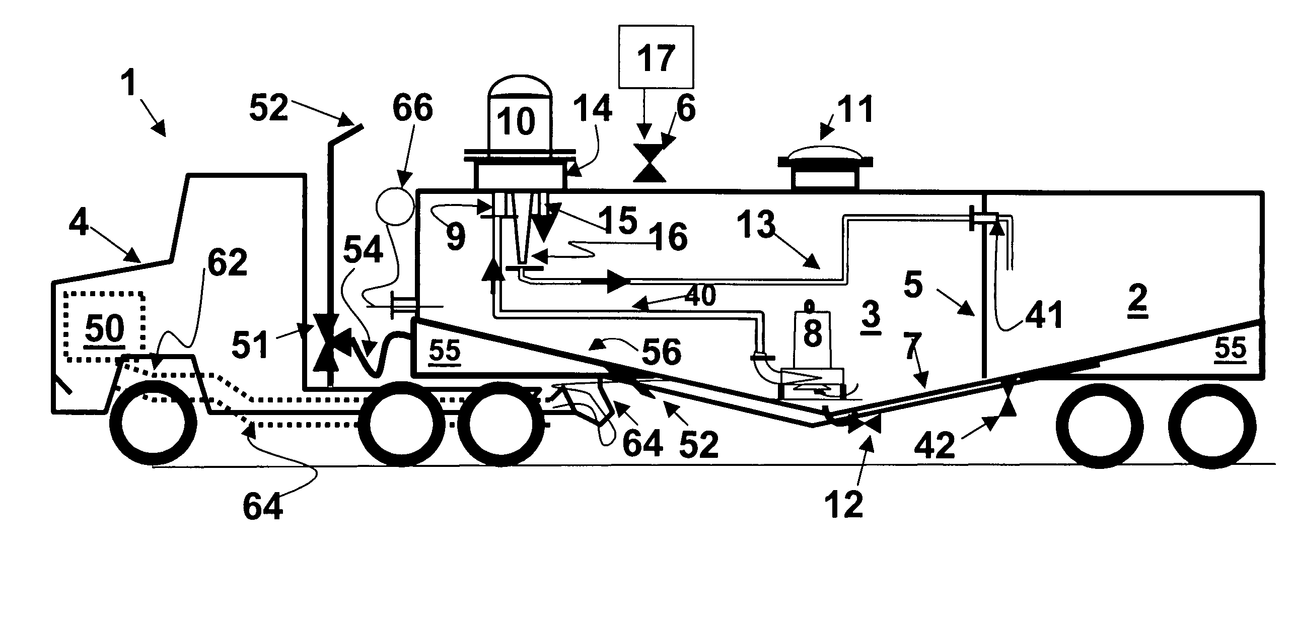
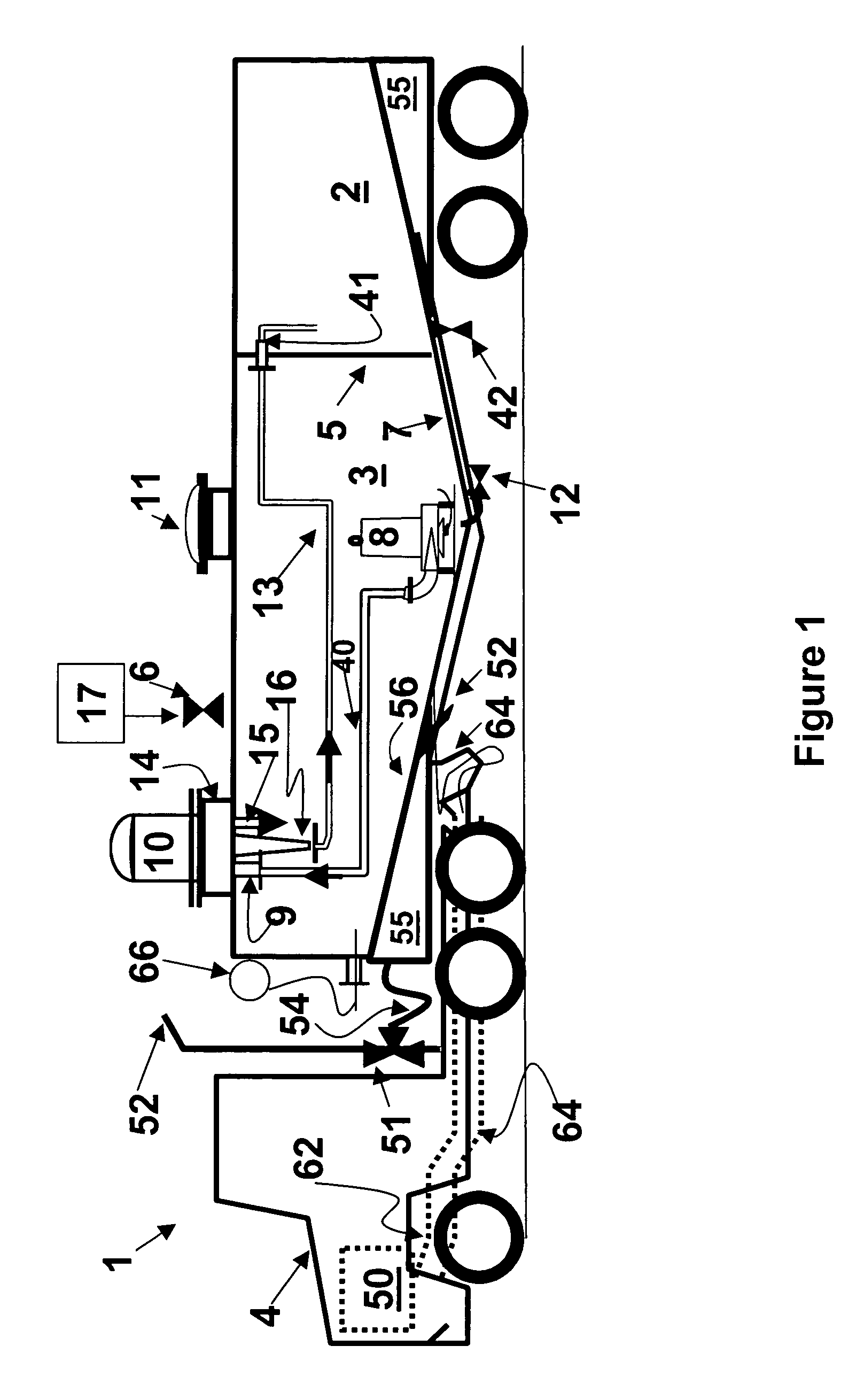
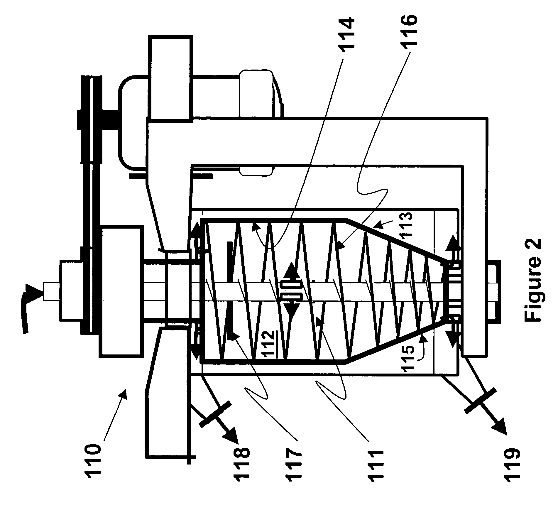
[0054]A portable tank with an empty mixed organic / aqueous compartment and an empty separated aqueous container is connected to a grease trap containing wastewater, and the process of emptying the grease trap is initiated. The total contents of the grease trap are pumped into the mixed organic / aqueous compartment that is housed on a truck bed. After the hoses have been disconnected and the mixed organic / aqueous compartment is sealed, a grinder pump is set to recycle and the contents of the mixed organic / aqueous container are heated to a temperature of from about 60° C. to about 70° C. Once the contents of the mixed organic / aqueous container reach the temperature of about 60° C. to about 70° C., a centrifugal separator is actuated and the discharge from the grinder pump is directed to the centrifugal separator. The centrifugal separator separates the aqueous phase from the organic phase of the wastewater and the aqueous phase is piped into the separated aqueous container where the con...


PUM

PropertyMeasurementUnit
temperatureaaaaaaaaaa
diameteraaaaaaaaaa
diameteraaaaaaaaaa

Abstract

A wastewater separation system for separating an aqueous phase from an organic phase comprising oil, fat and / or grease in wastewater is disclosed. The wastewater may be collected from restaurant grease traps, as well as other food preparation facilities, schools, hospitals, processing plants and the like. A separator, such as a centrifugal separation device, comprises a wastewater inlet, an organic phase outlet for discharging low density liquid and solids and an aqueous phase outlet for discharging water and possibly other high density liquids and solids. The system can be portable and can be mounted on a vehicle for collection and treatment at various sites. Heat can be introduced to the system to accelerate the separation of the aqueous phase from the organic phase of the wastewater.

Description

CROSS REFERENCE TO RELATED APPLICATIONS[0001]This application claims the benefit of U.S. Provisional Patent Application Ser. No. 60 / 567,879 filed May 4, 2004, which is incorporated herein by reference.FIELD OF THE INVENTION[0002]The present invention relates generally to the separation devices, and more particularly relates to systems for separating the aqueous phase from the organic phase of wastewater.BACKGROUND INFORMATION[0003]Wastewater or “gray water” from food preparation facilities typically comprises grease, oil, fat and surfactants, collectively the “organic phase”, and water which may also contain food solids, the “aqueous phase”. The aqueous phase of wastewater can be easily passed through wastewater piping and treated by wastewater treatment systems, however, if the organic phase is allowed to enter sewer lines and wastewater treatment systems, it can form blockages in the wastewater piping, primary treatment systems, publicly owned treatment works (POTWs) and leach fie...

Claims


Application Information

Patent Timeline
Patent Type & Authority Patents(United States)
IPC IPC(8): B01D17/032B01D35/18C02F1/38C02F1/02C02F1/40
CPCC02F1/38C02F1/02C02F1/40C02F2103/32C02F2201/008
Inventor HILLS, BLAIR H.
Owner HILLS BLAIR H
Why Eureka
Try Eureka