Powered rope climbing apparatus

a technology of rope climbing and rope breaking, which is applied in the field of powered rope climbing apparatus, can solve the problems of limiting the operation ability of rope climbing, limiting the service life of rope climbing, so as to reduce the relative displacement of the apparatus, increase the frictional resistance, and enhance the frictional engagement of the rope breaking effect.

Inactive Publication Date: 2009-04-07
LATCHWAYS PLC (GB)
View PDF13 Cites 54 Cited by
  • Summary
  • Abstract
  • Description
  • Claims
  • Application Information

AI Technical Summary

Benefits of technology

[0025]The apparatus may further comprise at least one additional rope restraining mechanism biased into engagement with the rope so as to restrain displacement of the rope relative to the apparatus in a first direction whilst allowing relative displacement between the apparatus and the rope in a second opposite direction.
[0026]Such a restraint mechanism will usually be manually displaceable from a first position which is biased into engagement with the rope, to a second position out of engagement with the rope to allow displacement of the rope relative to the apparatus in either direction when the restraint mechanism is in the second position. Furthermore, it is preferred that the apparatus will comprise a manually displaceable switch member for operating the motor whereby such switch member will be operatively coupled with the restraint mechanism, such that manual displacement of the switch member from a first to a second position will effect corresponding displacement of the restraint mechanism from its first to its second position. Preferably such restraint mechanisms will comprise an ascender cam. In one preferred embodiment of the current invention the ascender cam will be provided with a cam bearer having a substantially concave surface for complimentary receipt of a convex surface of the cam member of the ascender cam. This concave surface may further be provided with gripping teeth, grooves or other surface irregularities for increasing frictional resistance and for restraining displacement of the rope in a first direction. Alternatively, the ascender cam may be provided with a substantially flat cam surface and the cam bearer may have a complimentary flat surface of complimentary design. By providing the cam bearer to have a complimentary shape to that of the cam member of the ascender cam compression of the rope is effected over a much greater area enhancing the extent of frictional engagement of the rope breaking effect of such ascender cam.
[0027]In addition, it is preferable that at least one of the rope input guide member and the rope output guide member will also comprise a rotatable pulley wheel which may be freely rotatable in a first direction, but which are restrained from rotational displacement in a second opposed direction. In this manner, these guide members may have free movement of the rope thereabouts in a first direction, but provide a frictional resistance to movement of the rope in the second direction. Here, for example, during ascent, the pulley wheels will be freely rotatable to allow the rope to pass thereover and thus not to provide any additional restraint during ascent, but during descent, frictional engagement between the rope and the non-rotating pulley wheels serve to restrict the relative displacement of the apparatus and assist in breaking during ascent.
[0028]Further according to the present invention, there is provided an ascender cam comprising a rotatably mounted cam member pivotally biased towards a cam bearer for compression of a rope passing therebetween, characterised in that said cam bearer has a rope engaging surface of complimentary shape to that of a rope engaging surface of said cam member. Preferably, where the cam member has a curved convex surface, the cam bearer has a complimentary concave surface. The surface of the cam bearer is preferably provided with rope engaging means such as teeth or indentations for increasing frictional engagement with the rope disposed between the cam bearer and the cam member, usually such that such engaging means engage with said rope only during relative displacement therebetween in a first direction.

Problems solved by technology

Rope climbing, whether professionally or recreationally can be extremely arduous and potentially dangerous and therefore numerous labour saving and safety devices have been developed to assist the climber.
In particular, for professional rope climbers who, through necessity of their jobs, must constantly ascend and descend the ropes (ie. for inspection or maintenance in inaccessible areas) this can be highly energy sapping and thus limit their operational ability.
Secondly, where additional material or additional bodies need to be carried by a climber (in the event of a rescuer) then the workload is significantly increased.
In addition, whilst traditional winches or hoists have been employed to take advantage of a power source to lower or raise an appropriate body or person suspended on a rope to enable them to ascend or descend to an inaccessible position, such devices are significantly limited in their operation due to their mass and necessity to be attached to a secure anchor point (often necessitating bolting or other securely fixing).
A further drawback of such traditional hoists and winches is that they cannot be releasably connected along a length of rope, but instead a rope must be threaded end first through the mechanism significantly restricting the application of these devices to assist a user and restricting their ability to be connected to any part of a rope, particularly to the midpoint of a suspended rope.

Method used


Image

  • Powered rope climbing apparatus
  • Powered rope climbing apparatus
  • Powered rope climbing apparatus

Examples


first embodiment

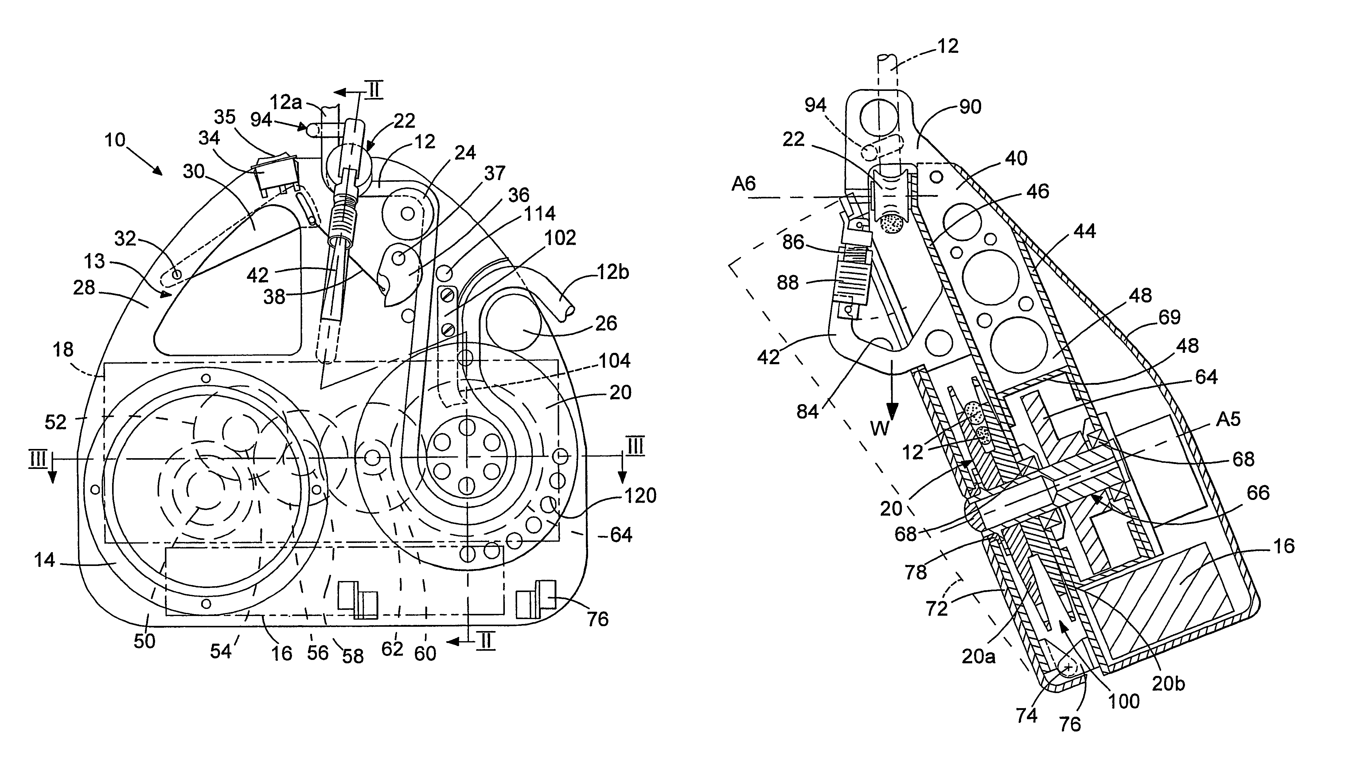
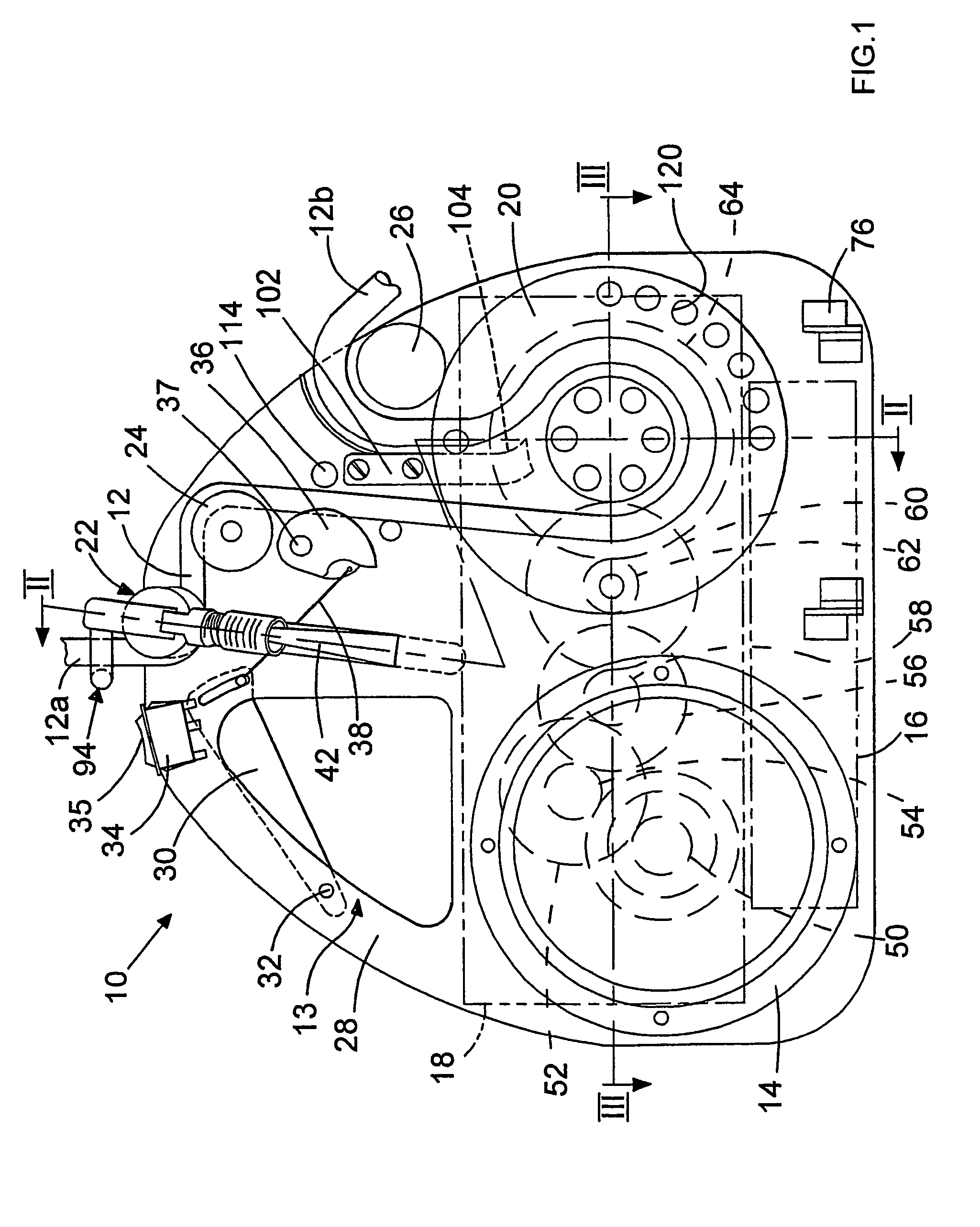
[0099]Referring now to FIG. 4, the pulley 24 of the embodiment shown in FIG. 1 has now been omitted so that he rope 12 extends directly between the guide wheel 22 mounted on the karimber 42 and the main pulley wheel 20. Since the entry path of rope 12 into the pulley wheel 20 has now been modified, the position of the output pulley wheel 26 has been adjusted so as to ensure that the rope 12, as it exits the main pulley 20, is as close to the rope 12 as it enters this pulley wheel 20 as clearly shown in FIG. 4 and the importance of which was described with reference to the This has also necessitated modification of the design and orientation of the rope extractor 102 and its associated cam surface 104. The modification in the path of the rope 12 within the device 10 has also necessitated a change in position of the ascender cam 36, although this cam 36 is again directly connected to the trigger switch 30 by use of an appropriate wire mechanism. However, in this embodiment, the ascen...

embodiment 10

[0102]A further variation of the embodiment 10 shown in FIG. 4 is the modification to the karimber design, as best seen in FIG. 5, wherein an additional attachment mechanism is provided on top of the harness attachment member 42. This is provided by means of an extender plate 133 integrally formed with and extending vertically upwards (when viewed in FIG. 5) from the harness attachment member 42. This plate 133 is provided with a transversely extending hole 135 through which the rope 12 may be fed so as to provide a double pull loop arrangement of the rope as is conventional for winches. In this manner, and as illustrated in FIG. 4, prior to the rope 12 entering the device 10 as rope 12a, a first loop of the rope 12c is fed through the aperture 135 and extends vertically away from the device 10 around a remote pulley wheel before entering the climbing device 10 at position 12a in the manner described with reference to FIGS. 1-3. The rope 12c may extend to an anchor point remote the ...


PUM


Abstract

Portable power driven rope climbing apparatus having a motor driving a gear reduction mechanism which drives a pulley wheel securing a rope extending thereabouts. A rope output guide member is provided for maintaining the rope in engagement with the pulley wheel an attachment mechanism for attaching an external load. The attachment mechanism comprises a rope entry guide member for supporting a rope as it enters the apparatus, so as to provide a fulcrum point about which the mass of the apparatus exerts a first moment. The attachment mechanism further comprises a seat member for supporting the load. The seat member is held remote from the main body such that the load, when mounted thereon exerts a second, opposed moment about the fulcrum.

Description

[0001]THIS APPLICATION IS A CONTINUATION OF PCT INTERNATIONAL APPLICATION PCT / GB / 2004 / 000301 FILED Jan. 23, 2004 WHICH IS CURRENTLY PENDING AND CLAIMS PRIORITY OF GREAT BRITAIN PATENT APPLICATION GB 0301725.8, FILED Jan. 24, 2003.BACKGROUND OF THE INVENTION[0002]The present invention is directed to a powered rope climbing apparatus and, more particularly to a portable device which may engage and automatically climb a rope whilst allowing an operator to connect themselves thereto to appropriately ascend or descend a rope using such apparatus.[0003]Rope climbing, whether professionally or recreationally can be extremely arduous and potentially dangerous and therefore numerous labour saving and safety devices have been developed to assist the climber. For example, many specialised rope clamps and pulleys have been developed for both recreational and professional climbing which may be attached to the users harness and also to the rope which allows the user to selectively move these harn...

Claims


Application Information

Patent Timeline
Patent Type & Authority Patents(United States)
IPC IPC(8): A63B27/00A62B1/06B66D1/74
CPCB66D1/7415A62B1/06
Inventor CALVER, TREVER
Owner LATCHWAYS PLC (GB)
Why Eureka
Try Eureka