[0016]The present invention includes improved valve guide and spring retainer assemblies for use in plunger pump housings having an outwardly flared transition area in the suction bore. Alternative valve guide and spring retainer assemblies of the present invention are for use in plunger pump housings having an outwardly flared transition area in the discharge bore as well as the suction bore. Note that an outwardly flared transition area in the suction bore (together with an outwardly flared transition area in the discharge bore in alternative embodiments) allows relatively easier
insertion and removal of portions of improved valve guides and spring retainer assemblies in these areas.
[0021]Field maintenance is facilitated for pumps incorporating the plunger pump housings and improved valve guide and spring retainer assemblies of the present invention. Specifically, the requirement for maintaining precise alignment as to rotation and angle of entry during
insertion and removal of the DVLSG-II, the TDBS and / or the SVTSG-SR-II is relaxed. Additionally, one or more O-rings on an SVTSG-SR-II, a DVLSG-II or a TDBS can assist in retaining these structures temporarily in their respective outwardly flared bore transition areas during pump
assembly. And O-rings on an SVTSG-SR-II have a self-centering function that makes the use of top-stem-guided suction valves more efficient and practical.
[0026]An alternative illustrated embodiment of a plunger pump housing of the present invention comprises a discharge bore comprising a portion with substantially circular cross-sections and a second centerline for accommodating, e.g., a circular discharge
valve seat, followed by a transition area that is not necessarily outwardly flared. Note that the first and second centerlines are colinear, and that a discharge bore shoulder may be either present or absent. If the discharge bore shoulder is absent in this embodiment, stress in the pump housing is thereby reduced.
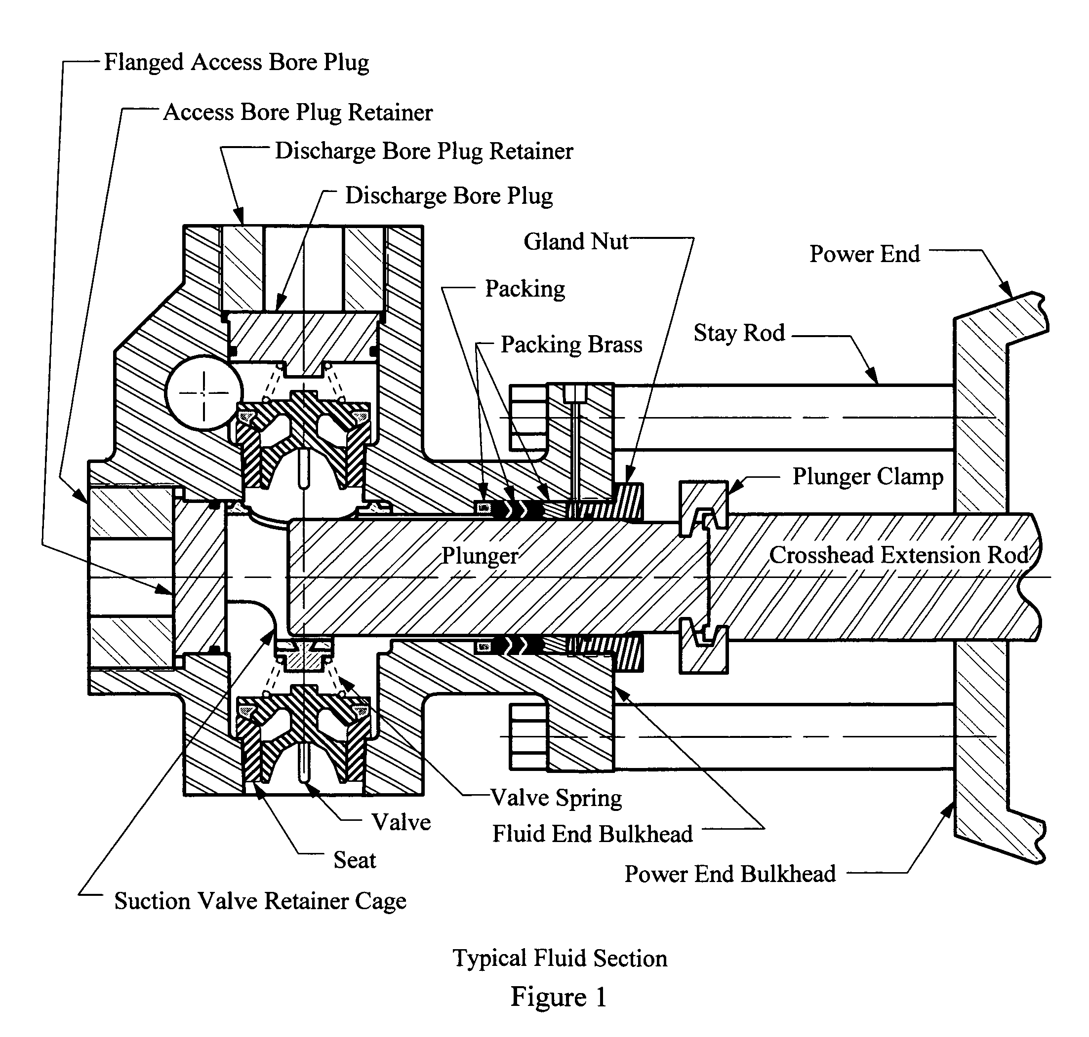
[0028]Illustrated embodiments of plunger pump housings of the present invention further comprise an access bore comprising a distal retainer portion with substantially circular cross-sections and a fourth center line. The distal retainer portion accommodates an access bore plug retainer and is followed by a proximal transition area having elongated cross-sections that can be sealed with a removable (flanged or flangeless) access bore plug. An access bore shoulder is located between the distal retainer portion and the proximal transition area. Removal of the access bore plug facilitates access to interior portions of the plunger pump housing. The access bore proximal transition area may be cylindrical or, in alternative embodiments, it may be inwardly flared (i.e., the proximal transition area may have a first predetermined inward taper extending from the access bore shoulder). Removal and replacement of an access bore plug having a
peripheral inward taper corresponding to the first predetermined inward taper of such an access bore transition area is easier than performing these operations with a cylindrical access bore
plug in a cylindrical access bore transition area. However, maintenance of precise alignment as to rotation and angle of entry or removal of such a cylindrical access bore plug can still be achieved during routine maintenance because of the relatively exposed location of the access bore plug. Thus, the choice of a cylindrical or tapered configuration for an access bore plug and a corresponding access bore transition area may additionally involve considerations such as the cost of
machining these structures. Note that as further described below, one illustrated embodiment of a flanged access bore side spacer-plug has an integral
flange (which bears on the access bore shoulder) and at least one integral side spacer, whereas an alternative illustrated embodiment of a flangeless access bore plug has neither an integral
flange nor an integral side spacer. The access bore's fourth centerline is colinear with the third centerline.
[0037]Simultaneous with this transmission of suction valve
spring force, self-centering of the DVLSG-II (or the TDBS) and the SVTSG-SR-II (or SVSR) will occur. Such self-centering is facilitated by one or more O-rings in
peripheral O-ring grooves. These O-rings and grooves are dimensioned to allow an increasingly close sliding fit as the DVLSG-II (or the TDBS) and the SVTSG-SR-II (or SVSR) are accommodated within their respective outwardly flared transition areas. Such
accommodation is achieved when, for example, the first predetermined outward taper of the suction bore transition area is equal to or slightly greater than the fifth predetermined
peripheral outward taper of the SVTSG-SR-II (or SVSR). Similarly, such
accommodation is achieved when, for example, the second predetermined outward taper of the discharge bore transition area is equal to or slightly greater than the third predetermined peripheral outward taper of the DVLSG-SR or the fourth predetermined peripheral outward taper of the TDBS. As the O-rings contact the respective outwardly flared transition areas, further
insertion is resisted due to increasing compression of the O-rings. Because such O-ring compression occurs substantially equally along each O-ring periphery, the resulting peripheral compressive forces tend to self-center the DVLSG-II (or the TDBS), as well as the SVTSG-SR-II (or SVSR) within their respective outwardly flared transition areas. Because of the resilience of the O-rings, this self-centering function is effective over a
small range of longitudinal, lateral and angular movement within each outwardly flared transition area. Thus, the DVLSG-II (or the TDBS) and the SVTSG-SR-II (or SVSR) can move slightly to accommodate small misalignments of the discharge and suction valve bodies and / or small misalignments of valve guide stems (due, e.g., to manufacturing tolerances). Note also that each side spacer may be dimensioned to fit closely between the plunger pump housing and a plunger inserted for use within the housing. By decreasing the amount of internal pump space that is not swept by the plunger, such close fitting of each side spacer can improve a pump's
volumetric efficiency.

