
Device having a tool holder and a tool which can be secured removeably

a tool holder and tool technology, applied in the direction of sleeve/socket joint, liquid dispensing, blast furnace, etc., can solve the problems of not allowing a solid to be directly into a reaction vessel, and the weighing of a defined quantity of substances is relatively complex, so as to increase the possible use of the device and achieve even more success.

Inactive Publication Date: 2009-04-07
CHEMSPEED TECH
View PDF32 Cites 16 Cited by
  • Summary
  • Abstract
  • Description
  • Claims
  • Application Information

AI Technical Summary

Benefits of technology

"The invention is a device that allows for automatic securing and removal of tools from a tool holder. The device includes a tool holder and various tools that can be automatically secured and removed using the tool holder. The tools can be moved independently of the tool holder, making it easier to handle different substances without getting in each other's way. The device also includes a storage container for the substance being metered, which can be attached to the tool holder. The tool holder can rotate in the z direction, allowing for more flexibility in arranging reaction vessels and starting-material bottles. The tools can be secured using magnets, screw connections, or clamping connections, and the use of a diaphragm and a ram ensures more accurate and uniform dispensing of substances. The device also includes a capsule-transporting head for picking up and releasing capsules, and a matrix-capsule-transporting head for picking up and releasing capsules in a matrix form."

Problems solved by technology

Although the two fixedly installed tools do make it possible to handle liquids and solids, they do not, for example, allow a solid to be metered directly into a reaction vessel.
Finally, accurate weighing out of a defined quantity of substance is relatively complex.

Method used


Image

  • Device having a tool holder and a tool which can be secured removeably
  • Device having a tool holder and a tool which can be secured removeably
  • Device having a tool holder and a tool which can be secured removeably

Examples


Embodiment Construction

FIG. 1

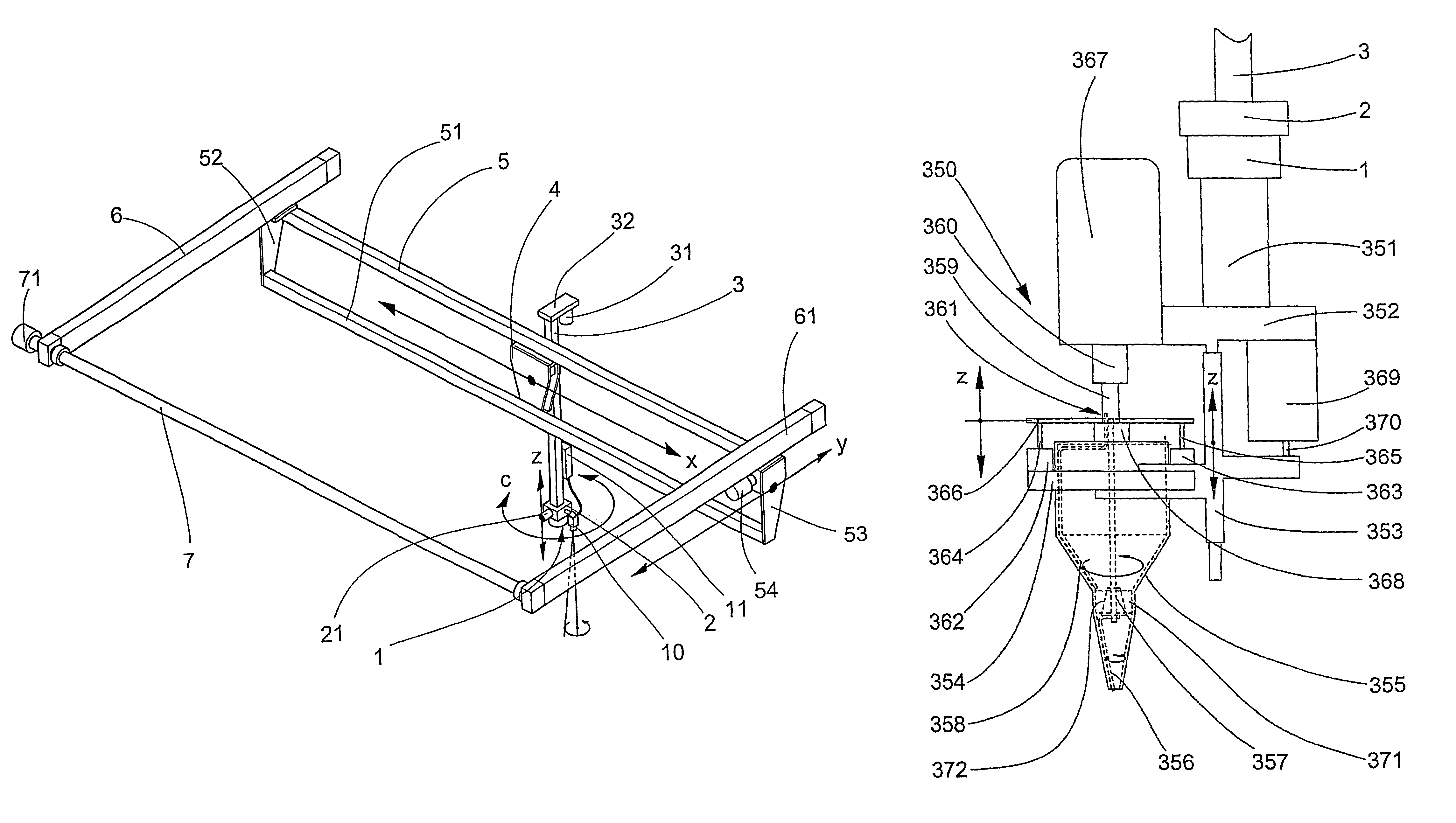
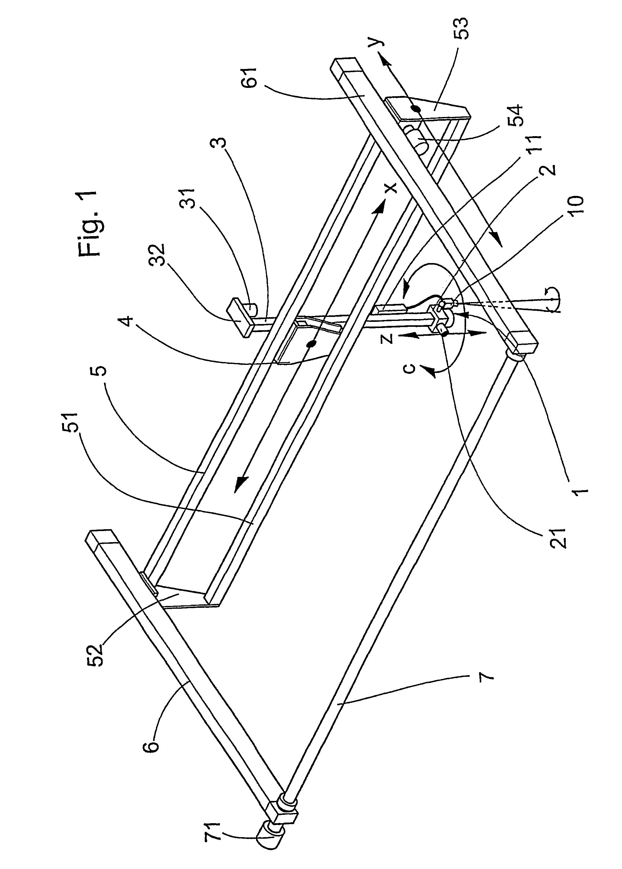
[0065]A linear axis system for holding and displacing a tool holder 1 comprises two guide rails 6, 61, which run parallel to one another in the y direction and are anchored in a fixed position in a manner which is not illustrated. The first ends of the two guide rails 6, 61 are connected by a rotary rod 7, which can be rotated by means of a stepper motor 71. An upper running rail 5 is secured to the two guide rails 6, 61 in such a manner that it can be displaced in the y direction. The upper running rail 5 is fixedly connected to a lower running rail 51 by means of two end plates 52, 53. As a result of the rotary rod 7 being rotated by means of the stepper motor 71, in each case one toothed belt in the interior of the guide rails 6, 61 is driven, causing the running rails 5, 51 to be displaced in the y direction. In the present context, the term displacement in the y direction is to be understood as meaning both a displacement in the +y direction and in the −y direction (the o...


PUM

PropertyMeasurementUnit
movementaaaaaaaaaa
displacementaaaaaaaaaa
distanceaaaaaaaaaa

Abstract

The inventive device comprises a tool holder, which can be displaced in an x-direction, in a y-direction that is perpendicular thereto, and in a z-direction that is perpendicular to both the x-direction and the y-direction, and which can rotate about the z-direction A solid matter dosing head, provided as a tool, is automatically attached in a removable manner to the tool holder by means of a permanent magnet. The tool can be easily exchanged for another tool due to this automatic removable attachment of said tool to the tool holder involving the use of a permanent magnet.

Description

BACKGROUND OF THE INVENTION[0001]The present invention relates to a device having a tool holder, which can be displaced in an x direction and a z direction which is perpendicular to the x direction, and a first tool in the form of a metering head, which can be removably secured to the tool holder.[0002]Devices of this type are used, inter alia, for automatically metering substances into a plurality of reaction vessels or test tubes which are arranged, for example, next to one another.[0003]In a device which is known as Caco-2 Assay produced by Mettler Toledo Bohdan, Greifensee, Switzerland, there are two tool holders with different tools. The tool holders can be displaced in a horizontal x direction, a horizontal y direction which is perpendicular to the x direction, and a vertical z direction which is perpendicular to the x and y directions, and in this way can serve reaction vessels arranged next to one another under the control of software. One of the tools is designed for meteri...

Claims


Application Information

Patent Timeline
Patent Type & Authority Patents(United States)
IPC IPC(8): B23Q3/155G01N35/00G01N35/10
CPCG01N35/0099G01N35/109G01N2035/00188G01N2035/1051Y10T483/17Y10S279/90Y10T483/11Y10T279/23Y10T436/2575Y10S483/901
Inventor GUELLER, ROLFSCHROER, JOSEFFRANK, PAULMETZGER, FRANZBACHMANN, CHRISTOPHKLOKOW, GERHARDEICHIN, STEFAN
Owner CHEMSPEED TECH
Learn More