Spindle motor and recording disk driving device including the same

a technology of spinning motor and recording disk, which is applied in the direction of dynamo-electric machines, instruments, structural associations, etc., can solve the problems of increasing the difficulty of reducing the thickness of the stator, increasing the difficulty of fabricating an inexpensive shield sheet, and high material cost of shield sheet b>5/b>, so as to reduce the thickness, reduce the cost, and reduce the size

Inactive Publication Date: 2009-04-07
NIDEC CORP
View PDF20 Cites 0 Cited by
  • Summary
  • Abstract
  • Description
  • Claims
  • Application Information

AI Technical Summary

Benefits of technology

[0010]It is an object of the present invention to provide a spindle motor with a reduced size, a reduced thickness and a reduced price and a recording disk driving device including the spindle motor.
[0011]It is another object of the present invention to provide a spindle motor with excellent reliability and durability and a recording disk driving device including this spindle motor.
[0015]With the spindle motor according to the example of the present invention, it is possible to realize size reduction, thickness reduction and price reduction of the shield sheet.
[0016]Further, with the present invention, since the shield sheet is formed to have an outer peripheral edge with a diameter smaller than that of the bridging wire engaging portions of the stator, the shield sheet does not cover the bridging wire engaging portions, which enables size reduction and price reduction of the shield sheet.
[0017]With the present invention, it is possible to provide a spindle motor with excellent reliability and durability and a recording disk driving device including this spindle motor.

Problems solved by technology

This increases the difficulty of reducing the thickness of the stator 4.
Furthermore, since the shield sheet 5 is formed to cover the entire stator 4 from thereabove and also to cover a stator fitting portion 6a of the housing 6, a high material cost is required for the shield sheet 5.
This increases the difficulty of fabricating an inexpensive shield sheet 5.

Method used


Image

  • Spindle motor and recording disk driving device including the same
  • Spindle motor and recording disk driving device including the same
  • Spindle motor and recording disk driving device including the same

Examples


first embodiment

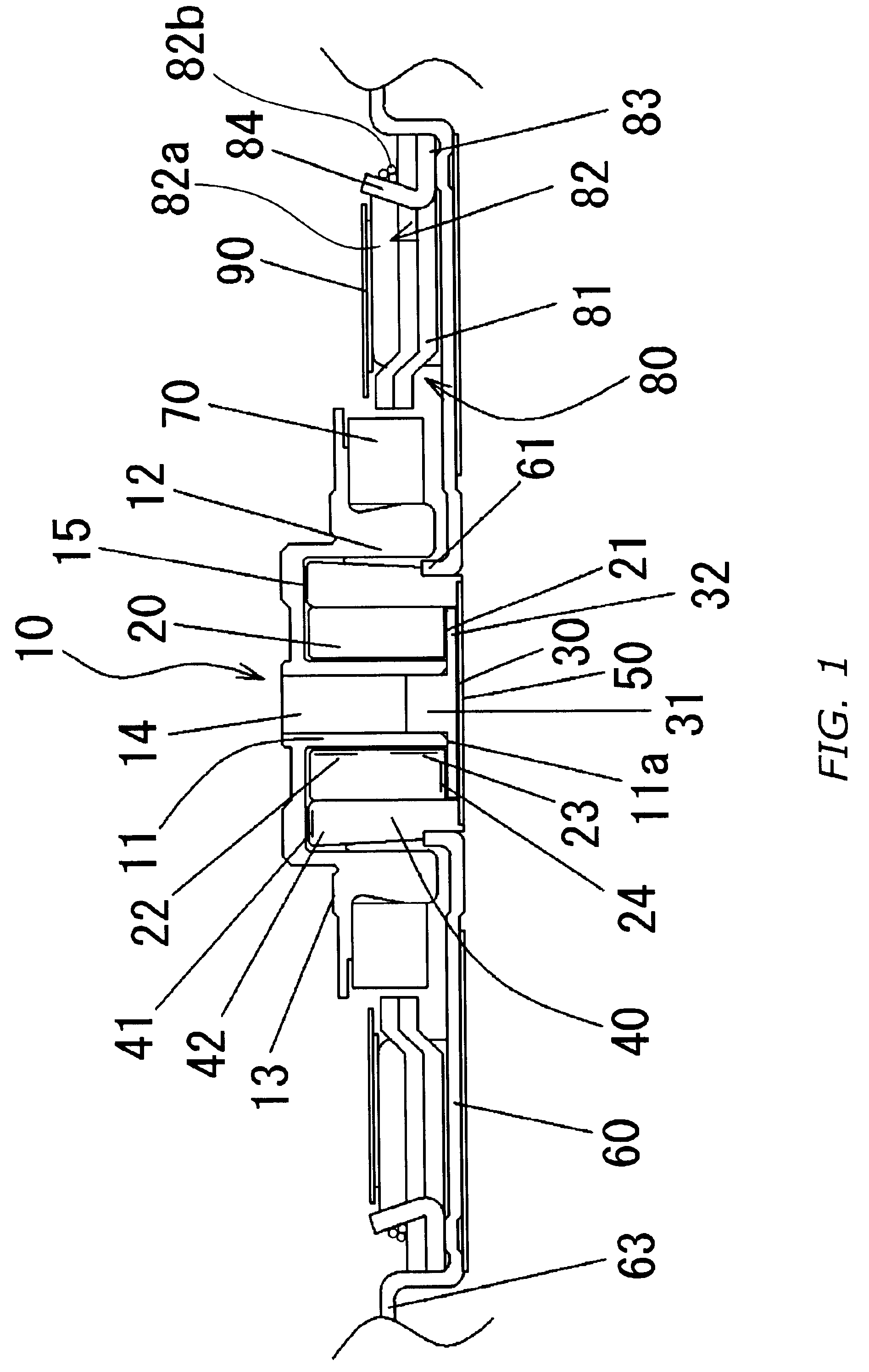
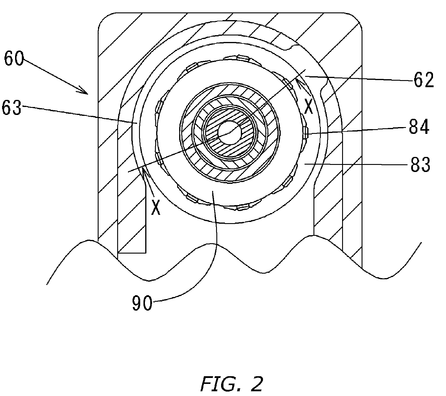
[0028]FIG. 2 is a main part top view of a spindle motor of FIG. 1 and FIG. 1 is a longitudinal cross-sectional view of the X-X cross section of FIG. 2 viewed in the direction of arrows. A rotor hub 10 includes a shaft 11 and an outer cylindrical portion 12, and a disk mounting portion 13 for mounting a magnetic disk such as a hard disk thereon is formed at the upper side of the outer cylindrical portion 12. A rotor magnet 70 with annually arranged magnetic poles is retained on an outer peripheral surface of the outer cylindrical portion 12 through a means such as adhesive.

[0029]A hollow cylindrical-shaped sleeve 20 is faced to an outer peripheral surface of the shaft 11 with a radial gap interposed therebetween, an lower end surface 11a of the shaft 11 is positioned slightly below an lower end surface 21 of the sleeve 20 in the axial direction.

[0030]A pull-out preventing member 30 is secured to the shaft 11, in order to prevent the rotor hub 10 from being pulled out from the shaft 2...

second embodiment

[0045]With reference to FIG. 3 and FIG. 4, a shield sheet according to a second embodiment of the present invention will be described. FIG. 4 is a main part top view of a spindle motor of FIG. 3. FIG. 3 is a longitudinal cross-sectional view of the Y-Y cross section of FIG. 4 viewed in the direction of arrows. The spindle motor according to the second embodiment has the same basic configuration as that of the spindle motor according to the first embodiment. As illustrated in FIG. 3 and FIG. 4, a shield sheet 190 is placed radially outside of the rotor magnet 70 such that the shield sheet 190 is faced to the rotor magnet 70 with a gap interposed therebetween. The shield sheet 190 is formed to have different two diameters. An outermost peripheral edge 193 of the shield sheet 190 is provided radially inside of an respective bridging wire engaging portions 84. At the portions of the shield sheet 190 which overlap with an plurality of teeth 181 in the axial direction, there are formed a ...

third embodiment

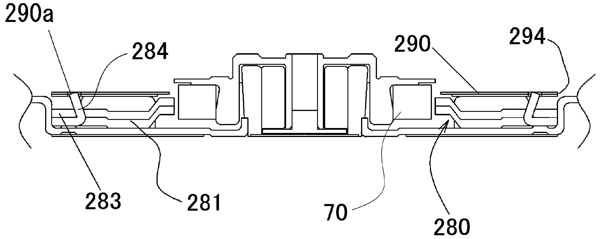
[0050]With reference to FIG. 5 and FIG. 6, a shield sheet according to a third embodiment will be described. FIG. 6 is a main part top view of a spindle motor of FIG. 5. FIG. 6 is a longitudinal cross-sectional view of the Z-Z cross section of FIG. 6 viewed in the direction of arrows. The spindle motor according to the third embodiment has the same basic configuration as that of the spindle motor according to the first embodiment.

[0051]A shield sheet 290 is placed radially outside of the rotor magnet 70 such that the shield sheet 290 is faced to the rotor magnet 70 with a gap interposed therebetween. An outermost peripheral edge 294 of the shield sheet 290 is substantially the same as that of an outer peripheral edge of the core back 283. At the portion of the shield sheet 290 which axially overlap with an respective bridging wire engaging portions 284, the shield sheet 290 is partially cut out to form an shield sheet cutout portions 290a. An tip end portions of the respective bridg...


PUM


Abstract

A spindle motor in one inventive implementation includes a rotor hub (10) for retaining a rotor magnet (70) and a stator (80) which is faced to the radial inner side of the rotor magnet (70) with a gap interposed therebetween. A shield sheet (90) is placed between the upper side of the winding (82) of the stator (80) and the disk mounting portion (13) of the rotor hub (10) and the outer peripheral edge of the shield sheet (90) is placed radially inside of the outer peripheral edge of the core back (83) of the stator (80).

Description

BACKGROUND OF THE INVENTION[0001]1. Field of the Invention[0002]The present invention relates to an inner-rotor type spindle motor which rotates and drives a magnetic disk such as a hard disk and a recording disk driving device including the spindle motor.[0003]2. Background Art[0004]FIG. 8 illustrates an inner-rotor type spindle motor including a conventional magnetic shield sheet. FIG. 8 is an axial cross-sectional view, wherein the vertical direction in the figure represents the axial direction. FIG. 9 is a main part top view of the spindle motor of FIG. 8 viewed from above.[0005]The spindle motor includes a stationary assembly 1, a bearing 2, and a rotor assembly 3 which is rotatably supported by the bearing 2.[0006]The stationary assembly 1 includes a stator 4 and an annular-shaped shield sheet 5. The shield sheet 5 is placed above the stator 4 to prevent magnetic fluxes generated from the stator 4 generally during driving from being largely leaked to the region above the shiel...

Claims


Application Information

Patent Timeline
Patent Type & Authority Patents(United States)
IPC IPC(8): H02K5/12
CPCG11B19/2009H02K1/146H02K5/10H02K11/0005H02K11/014
Inventor TAMAOKA, TAKEHITO
Owner NIDEC CORP
Why Eureka
Try Eureka