Exponential function generator and variable gain amplifier using the same

a technology of function generator and variable gain amplifier, which is applied in the direction of electric variable regulation, process and machine control, instruments, etc., can solve the problems of difficult stability maintenance, low usable voltage range in this structure, and affecting temperature voltage vsub>t /sub>,

a technology of function generator and variable gain amplifier, which is applied in the direction of electric variable regulation, process and machine control, instruments, etc., can solve the problems of difficult stability maintenance, low usable voltage range in this structure, and affecting temperature voltage vsub>t /sub>,

US7514980B2Inactive Publication Date: 2009-04-07SAMSUNG ELECTRO MECHANICS CO LTD

Image

  • Exponential function generator and variable gain amplifier using the same
  • Exponential function generator and variable gain amplifier using the same
  • Exponential function generator and variable gain amplifier using the same

Examples


Embodiment Construction

[0044]The following description will present an exponential function generator and a variable gain amplifier using the same with reference to the accompanying drawings.

[0045]In the present invention, the exponential function graph required in the variable gain amplifier is divided into a plurality of sections, and the curve of each section is represented by the most approximate linear graph, thereby forming the most approximate exponential graph. As the sections are made narrower, the exponential function graph becomes a closer approximation to the ideal exponential graph.

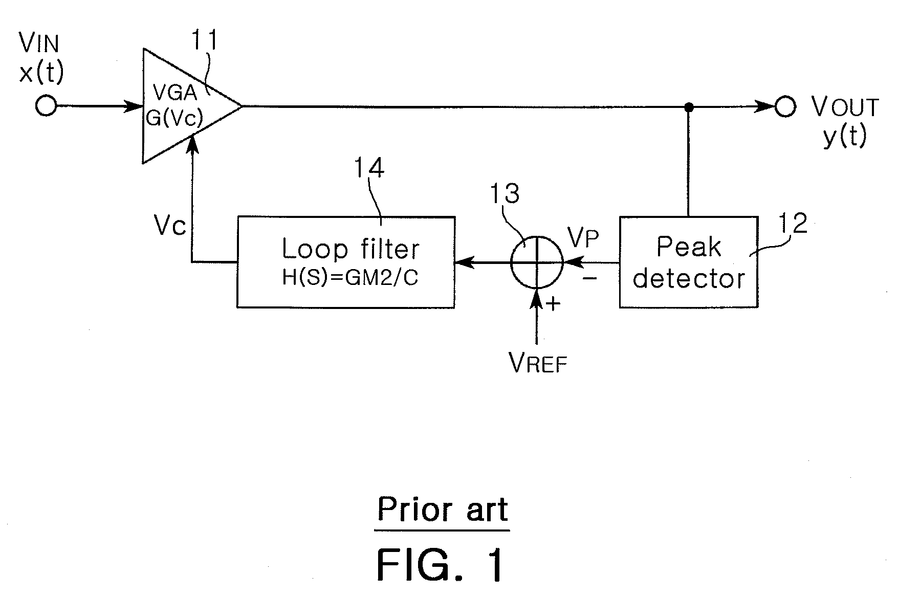
[0046]For example, the ideal exponential curve required in the variable gain amplifier (VGA) of the automatic gain control system, shown in FIG. 3, is divided into 6 sections. The input value Vc and the output value Iout corresponding respectively to the starting point and the ending point of each section are presented in following Table 1.

[0047]

TABLE 1Vc[V]Iout [μA]Iout{circumflex over ( )}[μA]0100.32.857730.68.16...


PUM


Abstract

The present invention relates to an exponential function generator which is realized with only CMOS element without BJT element, not limited by the physical properties of the element or a square circuit, and not complicated in its configuration, and a variable gain amplifier using the same. The exponential function generator includes a voltage-current converter, 1st to nth curve generators for mirroring the current from the voltage-current converter, outputting a current adjusted according to a predetermined ratio, and an output end for outputting the sum of the current from the 1st to nth curve generators. The exponential current generator is configured to generate the current exponentially adjusted according to the control voltage.

Description

CLAIM OF PRIORITY[0001]This application claims the benefit of Korean Patent Application No.2005-54496 filed on Jun. 23, 2005, in the Korean Intellectual Property Office, the disclosure of which is incorporated herein by reference.BACKGROUND OF THE INVENTION[0002]1. Field of the Invention[0003]The present invention relates to an exponential function generator which generates an exponential function signal to produce linearly variable gains and a variable gain amplifier using the same.[0004]2. Description of the Related Art[0005]In a Radio Frequency (RF) receiver with its flexible transmission environment, an input signal is variable in a wide range whereas an output signal needs to be in a uniform magnitude as a uniform magnitude of signal is required at the demodulation end. Thus, the RF receiver is used with an automatic gain control system which regulates the magnitude of the signal.[0006]FIG. 1 illustrates a basic concept of an automatic gain control system. The automatic gain co...

Claims


Application Information

Patent Timeline
07 Apr 2009
Publication
US7514980B2
IPC
G06F7/556; G06G7/20; G06G7/24
CPC
H03G7/001; H03G3/20
Inventors
CHOI, JEONG KI; BAEK, WON JIN