Crystal grating apparatus

a crystal grating and apparatus technology, applied in the field of measurement, filtration or separation of light, can solve the problems of two rays interfering with each other, limiting the usefulness of scanned optical signals, modulating light intensity, etc., and achieve the effect of reducing the spot size of ligh

Inactive Publication Date: 2009-04-07
SPECRYS
View PDF6 Cites 6 Cited by
  • Summary
  • Abstract
  • Description
  • Claims
  • Application Information

AI Technical Summary

Benefits of technology

[0112]According to still further features in the described preferred embodiments the polarization phase-shift is selected so as to minimize diffraction effects.

Problems solved by technology

While scanning spectrometers can exhibit very high spectral resolutions, the fact that they must be scanned limits their usefulness to the domain of optical signals whose spectrum does not change appreciably over the required scan time.
This causes modulation of light intensity due to interference between the two beams, such that each optical wavelength present in the input light generates its own modulation frequency.
The two rays then interfere with each other after passing through a polarizing analyzer.
Prior art spectrometers and wavelength meters suffer from limited resolution which is inherently imposed by the grating parameter or the refractive crystal characteristics.
In addition prior art spectrometers and wavelength meters have rather poor performances in cases where the beam of light is not fully collimated prior to the measurement.

Method used


Image

  • Crystal grating apparatus
  • Crystal grating apparatus
  • Crystal grating apparatus

Examples


example 1

Determination of Wavelength for a Monochromatic Light

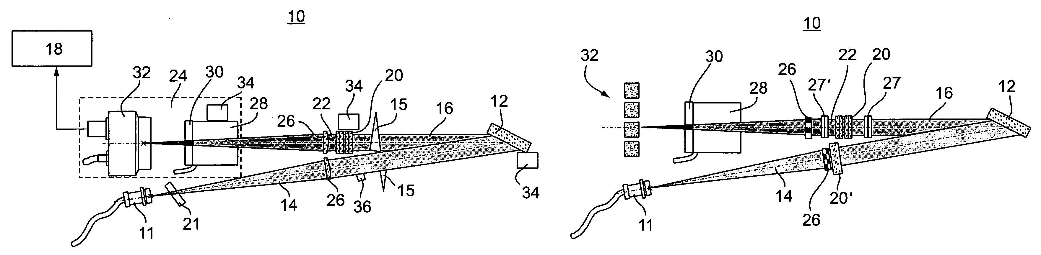
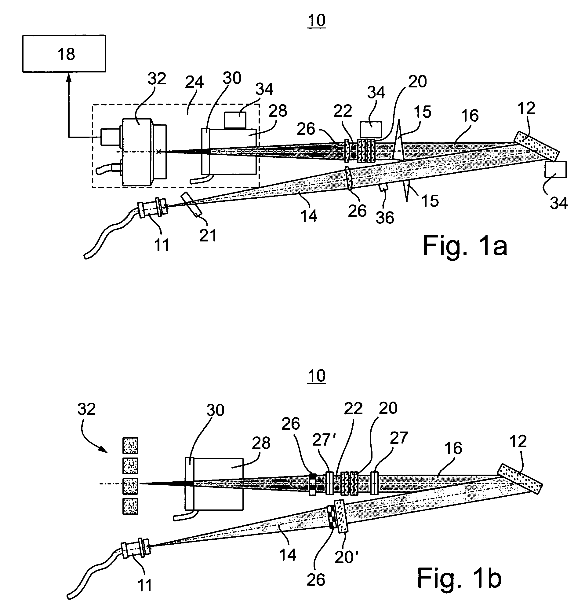
[0273]In its most simple configuration, apparatus 10 can serve as a wavelength meter for a monochromatic light, e.g., a laser light. When only a single wavelength is involved, the integration over the frequencies can be omitted and only one system parameter is preferably used. Thus, once the polarization phase-shift, ΔΦ′, is known (see Equation 8), the wavelength of the light can be extracted either by separated the light, e.g., using a beam splitter, into two detectors and calculating a contrast function, or, by employing the time-dependent polarization phase-shift, as further detailed hereinabove.

[0274]When extracting the wavelength using the contrast function, preferably wide bandwidth detectors are employed, up to GHZ, e.g., silicon or indium or gallium arsenide. In this embodiment, the response time of apparatus 10 is preferably in the GHz scale. Thus, apparatus 10 is capable of measuring transient phenomena unachievable with...

example 2

Determination of Wavelength for Multichromatic Light

[0283]As stated, apparatus 10 can be used as a spectrometer, for the purpose of analyzing a signal having large frequency content. In this case, the output, after the crystal valve, can be written, in the wavelength representation, as:

U=∫ cos2(ΔΦ(λ)+ΔΦvalve)I(λ)dλ,  (EQ. 23)

where the cos2 dependence is due to the intensity modulation. Using trigonometric properties one arrives at the following expression:

[0284]2⁢U=⁢∫[cos⁡(2⁢ΔΦ⁡(λ)+2⁢ΔΦvalve)+1]⁢I⁡(λ)⁢ⅆλ=⁢∫[cos⁡(2⁢ΔΦ⁡(λ))⁢cos⁡(2⁢ΔΦvalve)-⁢sin⁡(2⁢ΔΦ⁡(λ))⁢sin⁡(2⁢ΔΦvalve)+1]⁢I⁡(λ)⁢ⅆλ.(EQ.⁢24)

[0285]According to a preferred embodiment of the present invention ΔΦvalve as well as its dependence on time (e.g., periodic), is used so as extract the following individual terms from Equation 24.

Ucos(B)=0.5∫ cos((B(λ−λ0))I(λ)dλ

Usin(B)=0.5∫ sin((B(λ−λ0))I(λ)dλ

Uintg=0.5∫I(λ)dλ.  (EQ. 25)

[0286]In biological signals, the spectral dependence is typically modeled as a constant value plus a derivative. ...

example 3

Wavelength Meter and Multi-wavelength Meter

[0289]Apparatus 10 can be used as a wavelength meter to measure, detect or qualify sharp spectral lines, distribution of light with a central wavelength, derivative of a distribution of light, doublet lines (either sharp or distributed), known multipeaks distributions for a small number of peaks and the like.

[0290]The natural dispersion of the grating creates a channel effect. In other words, unlike prior are systems, the angular dispersion of the grating is not used to measure the wavelength value, but rather as a much coarser effect to separate the wavelength into channels in order to measure at once several wavelengths with a small gap therebetween. Whether the wavelengths are sparse or ordered on a grid the multi-wavelength meter provides as much information as a spectrometer with the same wavelength span.

[0291]FIG. 7 shows a spectrum, decoded by a multi wavelength meter, in which each peak is covered by a separate detector or detectors...


PUM

PropertyMeasurementUnit
timeaaaaaaaaaa
analysis timeaaaaaaaaaa
wavelengthsaaaaaaaaaa

Abstract

Apparatus for analyzing light having at least one wavelength, the apparatus comprising: (a) a light deflector for deflecting the light so as to provide a deflected light beam characterized by at least one wavelength-dependent angle, respectively corresponding to the at least one wavelength of the light; (b) an encoder, capable of encoding the deflected light beam so as to provide an encoded light beam characterized by at least one angle-dependent polarization state, respectively corresponding to the at least one wavelength-dependent angle; and (c) a decoder, for decoding the encoded light beam so as to determine at least one spectral component of the light.

Description

RELATED PATENT APPLICATION[0001]This application is a National Phase Application of PCT / IL2004 / 000057 having International Filing Date of 21 Jan. 2004, which claims the benefit of U.S. Provisional Patent Application No. 60 / 441,298 filed 22 Jan. 2003. The contents of the above Application are all incorporated herein by reference.FIELD AND BACKGROUND OF THE INVENTION[0002]The present invention relates to measurement, filtration or separation of light, and, more particularly, to wavelength measurement or separation of light according to its spectral components.[0003]Compact and cost-effective wavelength meters are in great demand for numerous applications, including instrumentation and wavelength division multiplexed (WDM) communications systems.[0004]An optical wavelength meter is an electronic instrument that measures the wavelength of a light signal input thereto. An optical multi-wavelength meter is one that can simultaneously measure the wavelengths of multiple signals of light su...

Claims


Application Information

Patent Timeline
Patent Type & Authority Patents(United States)
IPC IPC(8): G01J3/02G01J3/30G01J3/447G01N21/21
CPCG01J3/447G01N21/21
Inventor SIRAT, GABRIELNEUHAUSER, DANIELWILNER, KALMANVAKNIN, DAVID
Owner SPECRYS
Why Eureka
Try Eureka