Maskless, microlens EUV lithography system with grazing-incidence illumination optics

a lithography system and illumination optics technology, applied in the field of maskless, microlens euv lithography system with grazing-incidence illumination optics, can solve the problems of reducing optical efficiency, smaller lenses may be more difficult to manufacture, so as to improve illumination uniformity and minimize the effect of edge diffraction effects

Inactive Publication Date: 2005-06-09
JOHNSON KENNETH C
View PDF13 Cites 39 Cited by
  • Summary
  • Abstract
  • Description
  • Claims
  • Application Information

AI Technical Summary

Benefits of technology

[0008] In some embodiments, at least one mirror is apodized to minimize edge diffraction effects, which may be accomplished by a diffraction grating that performs the apodization disposed on a periphery of the mirror's surface. Similarly, in some embodiments, at least one mirror has a reflectance characteristic that i...

Problems solved by technology

Alternative, more complex designs (multi-element lenses, Bragg diffraction lenses, phase Fresnel lenses) could exhibit much better optical resolution and efficiency, but may be more difficult to manufacture.
On the other hand, several competing design factors weight against small lenses: (1) Smaller lenses may be more difficult to manufacture.
Consequently, optical resolution is not very sensitive to source size, but if the source is excessively large the spatial filtering action of the L2 aperture on off-axis source points will tend to broaden the PSF and reduce optical efficiency.
On the other hand, an excessively high dot density will adversely impact printing throughput.
Of greater concern are errors that are systematic across a printed image feature (i.e., the errors induced by different lenses are additive), but are non-systematic on a larger scale and hence cannot be corrected.
It may not be possible to correct high-order aberrations by this method, but the effects of such aberrations could, to some extent, be counterbalanced by inducing compensating low-order aberrations in the lenses.
A limitation of the two-element lens configuration of FIG. 17 is that the L2 optical absorption is greatly increased by the extra element, possibly necessitating a reduction in lens size and working distance to reduce the loss. FIG. 18 illustrates an ...

Method used


Image

  • Maskless, microlens EUV lithography system with grazing-incidence illumination optics
  • Maskless, microlens EUV lithography system with grazing-incidence illumination optics
  • Maskless, microlens EUV lithography system with grazing-incidence illumination optics

Examples


Embodiment Construction

[0051] Table of Contents

[0052] The following Table of Contents is provided to aid the reader in referring to specific portions of the specification. [0053] Illumination Source [0054] Microlens Design [0055] Microlens Optical Performance [0056] Print Quality [0057] Microlens Manufacture and Alternative Designs [0058] Printhead and Wafer Module Configuration [0059] Printing Throughput and EUV Power Requirements [0060] Collection Optics [0061] Distribution Optics [0062] Edge Effects and Apodization [0063] Efficiency Tuning [0064] Spectral Filtering [0065] Control System Architecture [0066] References [0067] Conclusion

Illumination Source

[0068] The illumination source is preferably a xenon LPP source (Refs. 2 and 6), which is preferred over alternative sources because of its small source size (<100 micron). A much larger source would degrade optical resolution. Also, the LPP is a relatively “clean” source in terms of debris generation. (Plasma sources other than xenon might also be c...


PUM


Abstract

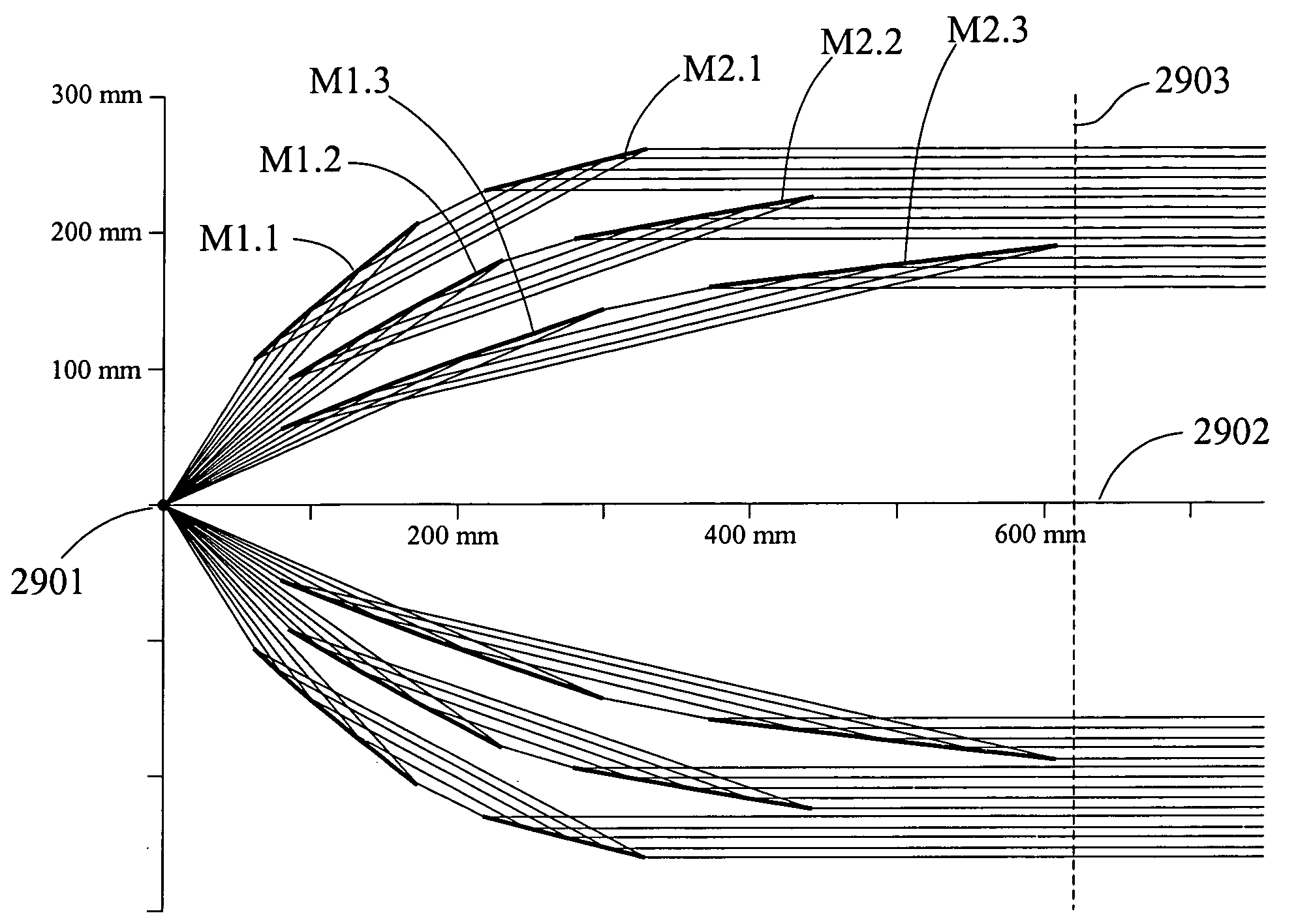
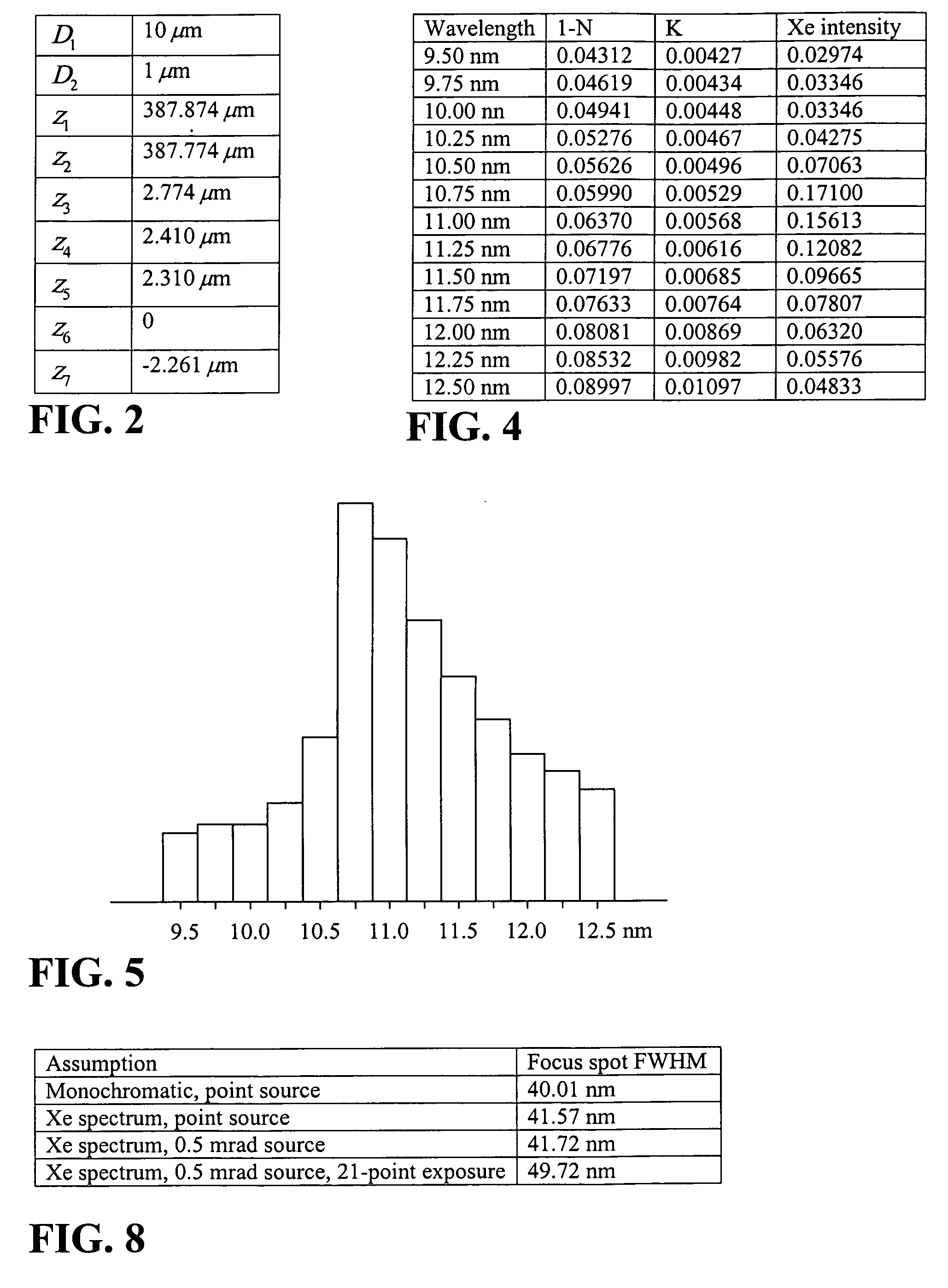
An EUV lithography system achieves high-resolution printing without the use of photomasks, projection optics, multilayer mirrors, or an extremely high-power EUV source. The system comprises a xenon laser-produced-plasma (LPP) illumination source (requiring 93 W hemispherical EUV emission in the wavelength range 10-12 nm), all-ruthenium optics (grazing-incidence mirrors and microlenses) and spatial light modulators comprising MEMS-actuated microshutters. Two 300-mm wafers are simultaneously exposed with a single 10 kHz LPP source to achieve a throughput of 6 wafers per hour, per LPP source. The illumination is focused by the microlens arrays onto diffraction-limited (42-nm FWHM) spots on the wafer plane, and the spots are intensity-modulated by the microshutters as they are raster-scanned across the wafer surface to create a digitally synthesized exposure image. The optical path between the source and the microlenses traverses seven grazing-incidence mirrors (two collimator elements and five fold mirrors), which have high reflection efficiency and essentially unlimited wavelength bandpass.

Description

CROSS-REFERENCE TO RELATED APPLICATION [0001] This application claims priority from U.S. Provisional Patent Application No. 60 / 527,106, filed Dec. 4, 2003, for “Maskless, Microlens EUV Lithography System with Grazing-Incidence Illumination Optics”, the entire disclosure of which is incorporated by reference.BACKGROUND OF THE INVENTION [0002] U.S. Pat. No. 6,498,685 (Ref. 1, incorporated herein by reference) disclosed an EUV lithography system comprising a xenon LPP (laser-produced plasma) illumination source, reflective illumination optics, microlens arrays, and microshutter SLM's (spatial light modulators), for achieving high-resolution, maskless printing. The illumination optics in the specific embodiment employed two Mo / Be (molybdenum / beryllium) multilayer mirrors for collimating the illumination. Mo / Be mirrors have a reflectance peak at 11.4 nm, which is well-matched to the xenon emission peak at 11 nm. Other prior-art EUV systems currently under commercial development (projecti...

Claims


Application Information

Patent Timeline
IPC IPC(8): G02B3/00G03F7/20
CPCB82Y10/00G03F7/70033G03F7/70233G03F7/70958G03F7/70291G03F7/70575G03F7/70275
Inventor JOHNSON, KENNETH C.
Owner JOHNSON KENNETH C
Why Eureka
Try Eureka