
Radio-controlled timepiece

a radio-controlled timepiece and timepiece technology, applied in the field of radio-controlled timepieces, can solve the problems of untuned tuning circuit, unfavorable rate of work, complicated work to assemble the radio-controlled timepiece,

Inactive Publication Date: 2009-04-07
SEIKO INSTR INC
View PDF10 Cites 11 Cited by
  • Summary
  • Abstract
  • Description
  • Claims
  • Application Information

AI Technical Summary

Benefits of technology

[0021]In addition, the variable-capacitance unit may include a rough adjustment part having roughly-adjusting capacitors different in capacitance value from each other, and a fine adjustment part having finely-adjusting capacitors smaller in capacitance value than the roughly-adjusting capacitors, and the control unit may combine the roughly-adjusting capacitors and finely-adjusting capacitors, thereby to change the capacitance value of the variable-capacitance unit.
[0033]The control unit may further change the capacitance value of the variable-capacitance unit so as to tune in to the radio signal at a previously decided time or a time of reset.

Problems solved by technology

That is, the adjustment performed by a combination of two or more capacitors makes the work to assemble the radio-controlled timepiece complicated and requires a long time and as such, the rate of work is unfavorable.
Therefore, the method to adjust the receiving sensitivity has the following problem.
That is, even when the adjustment is made to bring the tuning circuit into a tuning condition once, there is a high probability that tuning circuit falls into an untuned condition after having passed into the hands of a user, which deteriorates the receiving sensitivity.

Method used


Image

  • Radio-controlled timepiece
  • Radio-controlled timepiece
  • Radio-controlled timepiece

Examples


Embodiment Construction

[0043]A radio-controlled timepiece according to an embodiment of the invention will be described below.

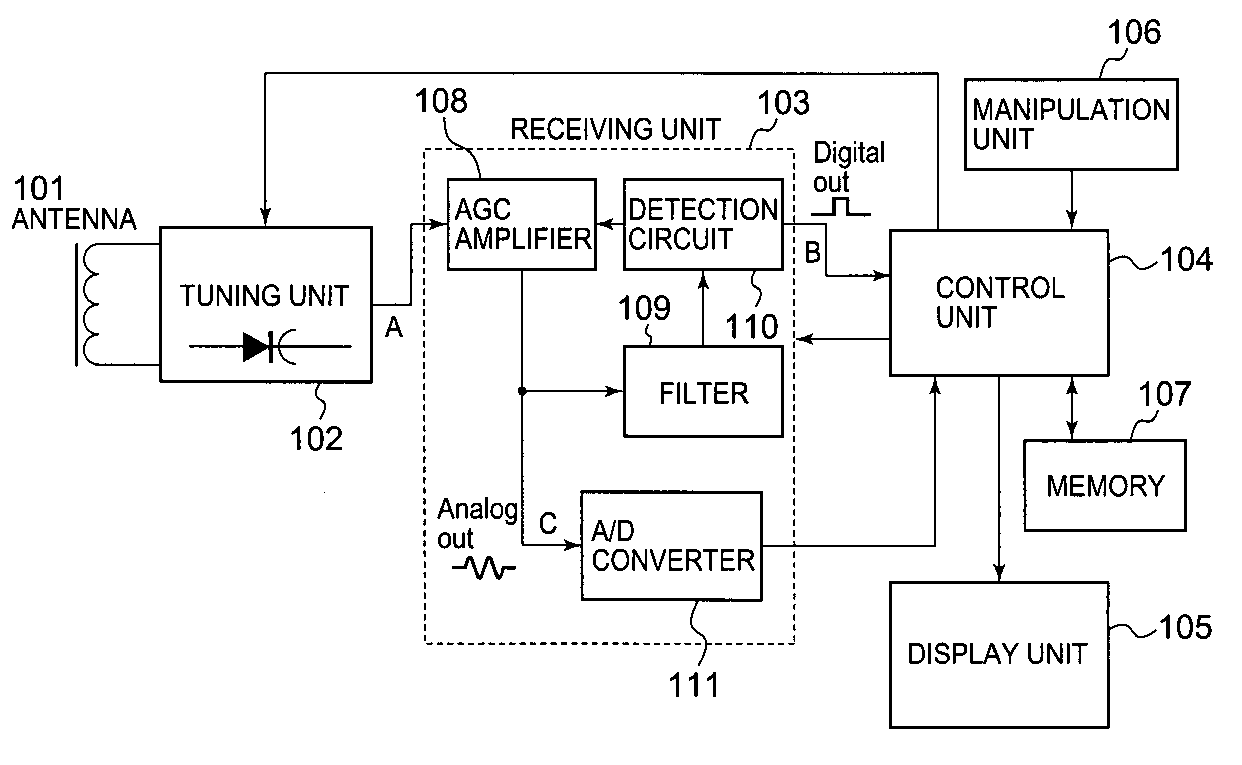
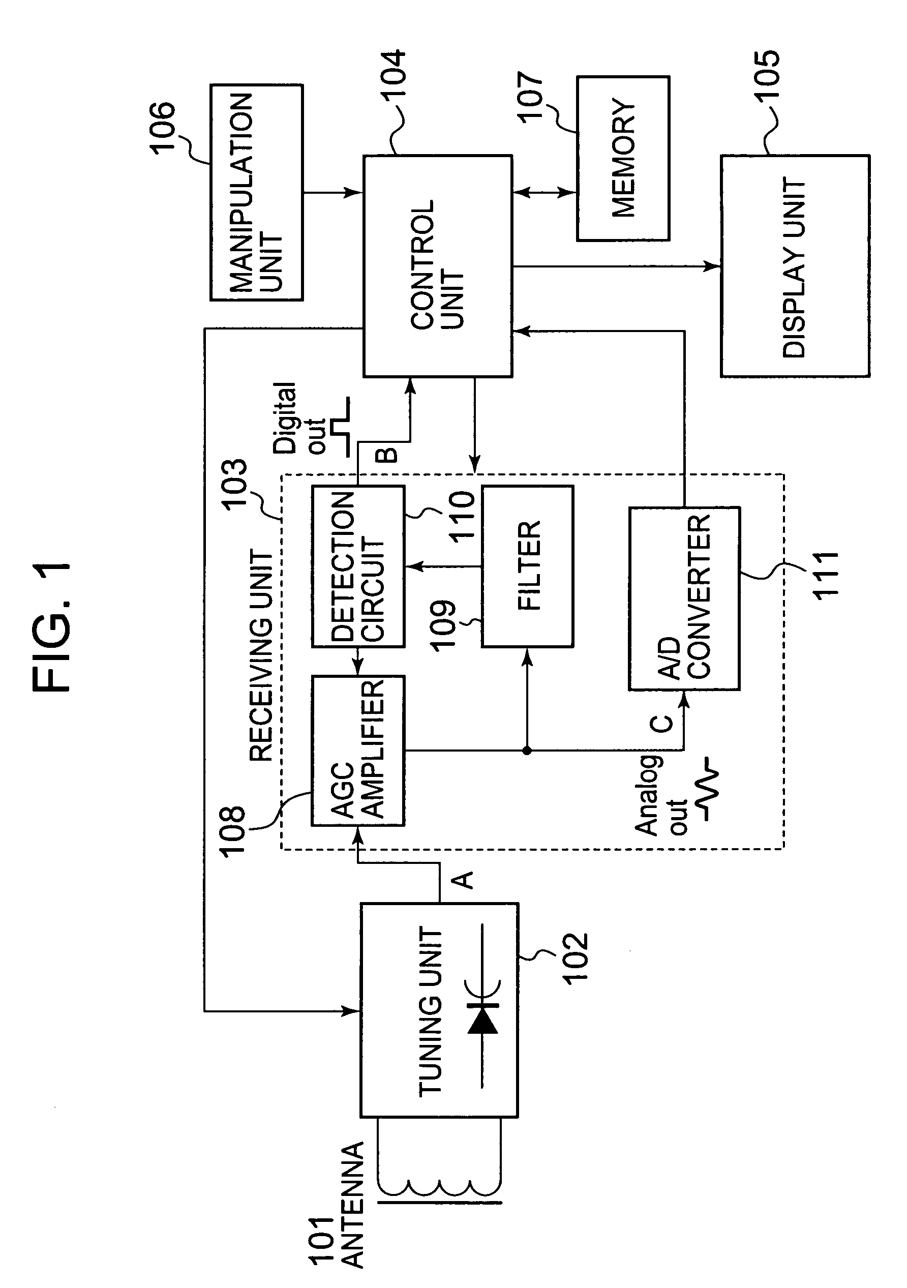
[0044]FIG. 1 is a block diagram of the radio-controlled timepiece according to the embodiment of the invention, which is an example of a radio-controlled timepiece that uses standard radio signals of Japan shown in FIG. 5 to correct time.

[0045]In FIG. 1, the radio-controlled timepiece has: an antenna 101 constituted by an antenna coil; a tuning unit having a variable-capacitance diode (varicap) 102 to change a tuning frequency; a receiving unit 103; a control unit l04 including a central processing unit (CPU) that performs control of constituent elements and the whole of the radio-controlled timepiece, etc.; a display unit 105 constituted by a liquid crystal display device or the like that displays the current time, etc.; a manipulation unit 106 including a manipulation switch or the like to e.g. provide instructions for a time-correcting process and a tuning operation; and a semic...


PUM


Abstract

In a radio-controlled timepiece, a tuning unit outputs a signal corresponding to a radio signal. An amplifier unit amplifies a signal output from the tuning unit. A receiving unit that extracts the time code from the amplified signal has a filter unit that selectively allows one of frequency signals to pass therethrough. A time-correcting unit acquires current time information from the extracted time code to correct a current time clocked by a clock unit. A control unit detects a voltage level of a signal output from the amplifier unit at two or more points while changing a capacitance value of a variable-capacitance unit of the tuning unit, uses, as a tuning point, a point meeting a given requirement among the points where the voltage level has been detected, and sets the capacitance value of the variable-capacitance unit at the tuning point as a capacitance value to receive the time code when it is judged that a time code has been output from the receiving unit at the tuning point. When it is judged that no time code is output from the receiving unit at the tuning point, the control unit controls the filter unit so as to change the frequency that the filter unit allows a signal to pass therethrough.

Description

BACKGROUND OF THE INVENTION[0001]1. Field of the Invention[0002]The present invention relates to a radio-controlled timepiece that corrects time based on time information that the timepiece received in radio waves.[0003]2. Description of the Prior Art[0004]A radio-controlled timepiece that receives radio signals indicating a precise time and automatically corrects time has been developed previously.[0005]Currently, in various countries (e.g. Germany, Japan, America, and England) a radio station placed at a given location sends out a standard low frequency radio wave with time information superposed thereon. In Japan, two transmitter stations send out 40-kHz and 60-kHz standard low frequency radio waves modulated in amplitude by a time code of a format as in FIG. 5.[0006]A radio-controlled timepiece, which receives the standard low frequency radio waves and corrects time data of a clock circuit, has been commercialized. In the case of a radio-controlled timepiece like this, it is equ...

Claims


Application Information

Patent Timeline
Patent Type & Authority Patents(United States)
IPC IPC(8): H04B1/18G04G5/00G04R20/00G04R20/10H03J7/08
CPCG04C9/02G04G5/002H03J3/185H03J5/244G04R20/10H03J2200/08H03J2200/10
Inventor SAITOH, YORITAKA
Owner SEIKO INSTR INC
Learn More