
Solar site selection apparatus and method

a technology of solar energy and site selection, applied in the field of solar site selection apparatus and methods, can solve the problems of increasing the cost of energy in the form of electricity and petroleum including fuels such as gasoline and diesel, natural gas and heating oil, and the need for enhanced recovery technology, so as to facilitate the adjustment of a site, and increase the solar energy potential of the site

Inactive Publication Date: 2009-04-14
COURTER ANTHONY
View PDF10 Cites 25 Cited by
  • Summary
  • Abstract
  • Description
  • Claims
  • Application Information

AI Technical Summary

Benefits of technology

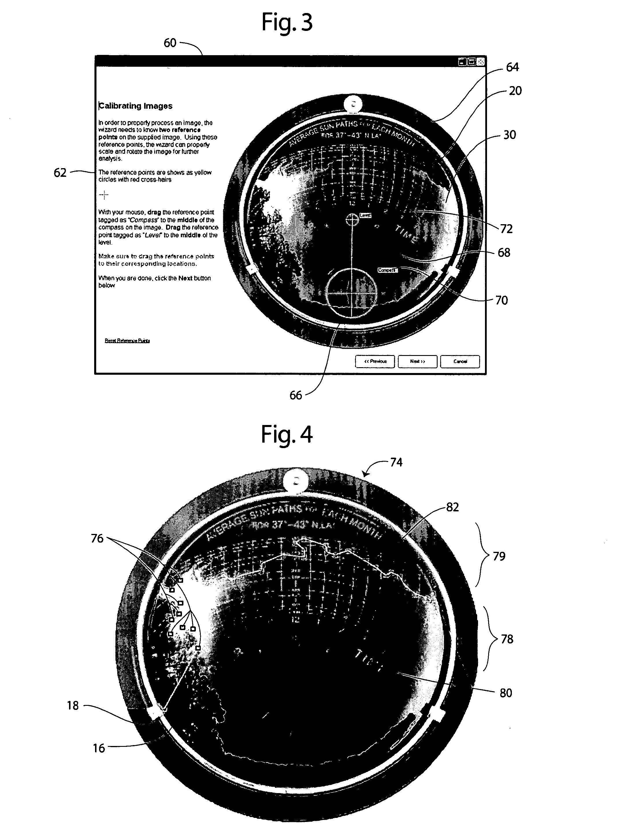
"The present invention provides an apparatus and method for evaluating and adjusting solar sites for improved solar energy potential. It uses a digital image of a sun trace on a solar dome at a site and analyzes the image to determine the orientation of the site and the potential solar exposure. The apparatus can adjust the image based on the magnetic declination of the site and the selected points on the sun trace to increase the solar energy potential. The invention also provides a solar exposure device with a compass and image receiver for obtaining a solar trace and determining the solar opportunity capacity for the site."

Problems solved by technology

Energy in the form of electricity and petroleum including fuels such as gasoline and diesel, natural gas, and heating oil, are becoming more expensive.
In addition, sources of energy products are becoming more difficult to obtain and require enhanced technology for recovering.
Coal plays an important role; however, coal also has intense labor requirements and necessary post burning filtering and cleaning of exhaust and water.
These alternate forms of electrical generation presently tend to be more expensive per kilowatt hour than more conventional sources.
While this approach reaches a solution as to potential solar opportunity, the solar site analysis tools experience drawbacks to its use.
The device and analysis is subject to error and is time consuming to use.
The analysis lack precision and flexibility of use, particularly for evaluating a site and making recommendations for changes in order to enhance the solar profile of the site.

Method used


Image

  • Solar site selection apparatus and method
  • Solar site selection apparatus and method
  • Solar site selection apparatus and method

Examples


Embodiment Construction

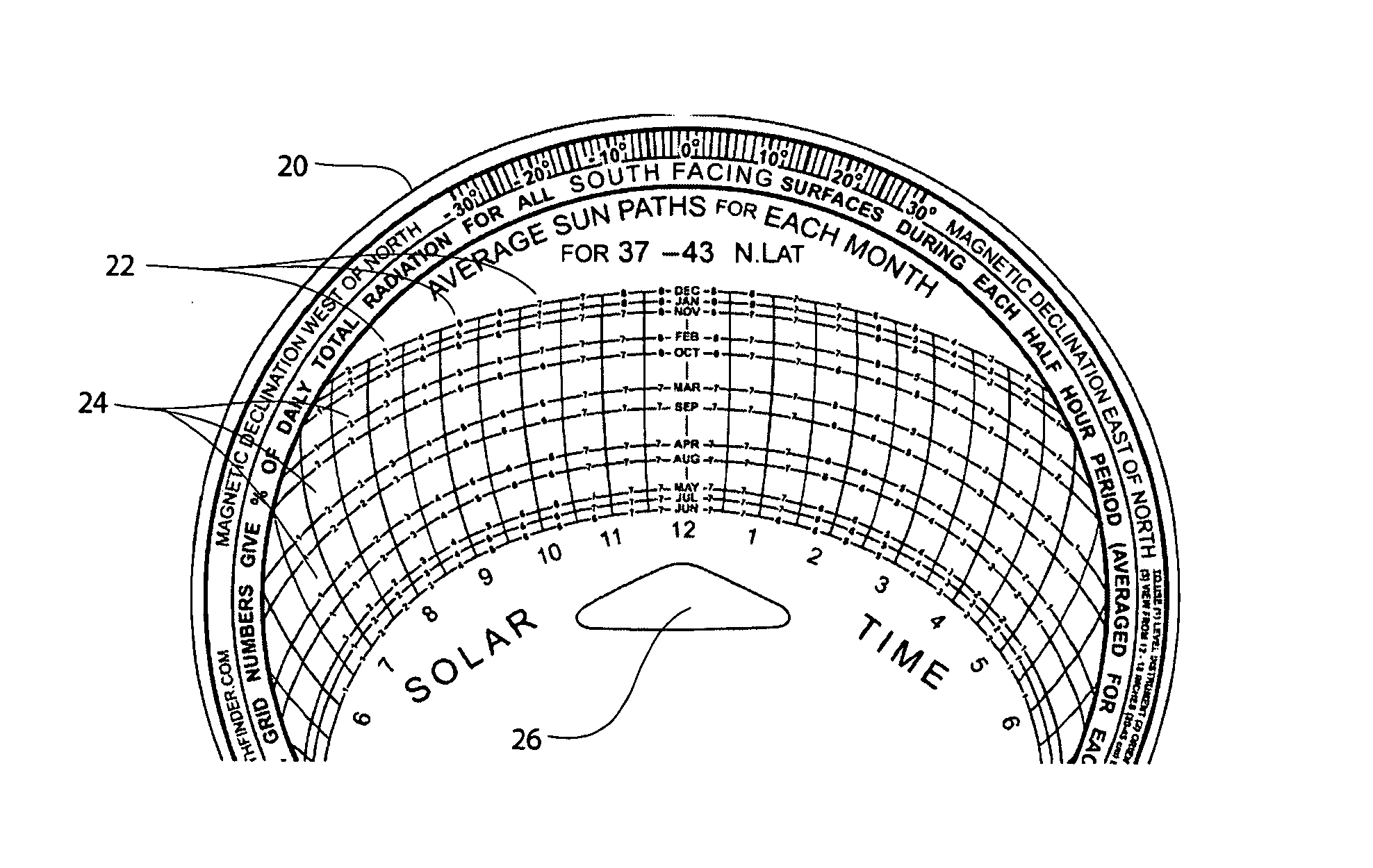
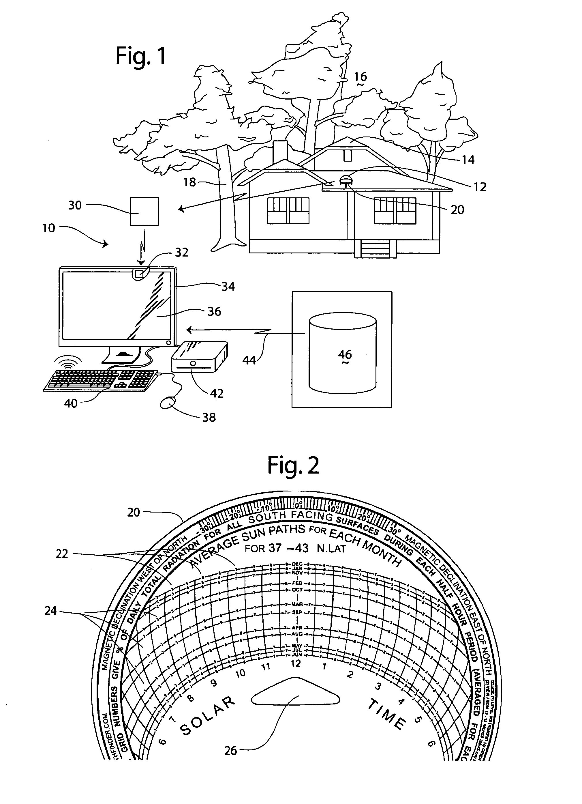
[0026]Referring now in more detail to the drawings, in which like reference numerals indicate like parts, FIG. 1 illustrates in schematic view a solar analysis system 10 according to the present invention. The system 10 includes a solar dome 12 that is positioned at a site such as a building or house 14. The site 14 includes a structure on which the solar collection panels (whether photovoltaic, water tube solar collection device, or the like) mount. The site includes a surrounding area generally 16 which includes a horizon and obstructions such as buildings, trees, and other geophysical features. The orientation of the building 14 relative to the area 16 obstructions affect the solar capacity of the site, which capacity is to be analyzed using the present invention. The solar dome 12 receives a sun path template 20 for recording a solar trace at the site.

[0027]With reference to FIG. 2, the sun path solar template 20 includes a plurality of columns 22 representing half hour incremen...


PUM


Abstract

An apparatus receives a digital image of a sun trace chart having time gradient lines and a sun trace extent line for a site. A selector defines on a display points along the solar trace extent line to define a solar opportunity region. An adjuster adjusts the digital image based on the magnetic declination of the site. The solar exposure potential is determined based on the proportion of solar trace extent lines within solar opportunity region and potential solar exposure. Site adjustments to increase solar energy potential are facilitated. A method of evaluating a site for solar energy potential is disclosed. A solar exposure device for recording and analyzing a solar trace is disclosed.

Description

TECHNICAL FIELD[0001]The present invention relates to solar site evaluation apparatus and methods. More particularly, the present invention relates to apparatus and methods that facilitate selection and adjustment of sites for reception of solar energy.BACKGROUND OF THE INVENTION[0002]Energy demands are increasing not only in the United States, but worldwide as well. Energy in the form of electricity and petroleum including fuels such as gasoline and diesel, natural gas, and heating oil, are becoming more expensive. This is in part due to increasing demand throughout the world notwithstanding efforts to conserve. In addition, sources of energy products are becoming more difficult to obtain and require enhanced technology for recovering. Refineries presently operate at close to capacity levels. Coal plays an important role; however, coal also has intense labor requirements and necessary post burning filtering and cleaning of exhaust and water. Nuclear electrical generation plants are...

Claims


Application Information

Patent Timeline
Patent Type & Authority Patents(United States)
IPC IPC(8): G04B49/02
CPCG01W1/12F24J2200/04F24S2201/00
Inventor COURTER, ANTHONY
Owner COURTER ANTHONY
Learn More