Impedance mating interface for electrical connectors

a technology of impedance mating and electrical connectors, which is applied in the direction of coupling device connection, electrical apparatus, coupling protective earth/shielding arrangement, etc., can solve the problems of difficult fine-tuning of impedance in a conductor, and the problem of general magnified problems, so as to achieve the effect of maximizing capacitance, improving performance, and minimizing impedan

Active Publication Date: 2009-04-14
FCI AMERICAS TECH LLC
View PDF150 Cites 11 Cited by
  • Summary
  • Abstract
  • Description
  • Claims
  • Application Information

AI Technical Summary

Benefits of technology

[0008]The invention provides for improved performance by adjusting impedance in the mating interface area. Such an improvement may be realized by moving and / or rotating the contacts in or out of alignment. Impedance may be minimized (and capacitance maximized) by aligning the edges of the contacts. Lowering capacitance, by moving the contacts out of alignment, for example, increases impedance. The invention provides an approach for adjusting impedance, in a controlled manner, to a target impedance level. Thus, the invention provides for improved data flow through high-speed (e.g., >10 Gb / s) connectors.

Problems solved by technology

Additionally, there may be times when matching the impedance in a connector with the impedance of a device is necessary to prevent signal reflection, a problem generally magnified at higher data rates.
Such fine-tuning of impedance in a conductor is a difficult task, usually requiring a change in the form or amount of dielectric material of the connector housing.

Method used


Image

  • Impedance mating interface for electrical connectors
  • Impedance mating interface for electrical connectors
  • Impedance mating interface for electrical connectors

Examples


Embodiment Construction

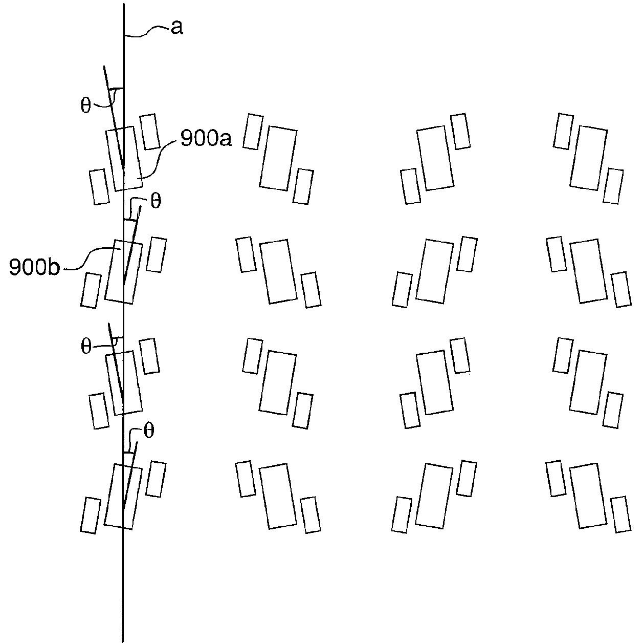
[0018]FIGS. 2A and 2B depict example embodiments of a header connector. As shown, the header connector 200 may include a plurality of insert molded leadframe assemblies (IMLAs) 202. FIGS. 3A and 3B are side views of example embodiments of an IMLA 202 according to the invention. An IMLA 202 includes a contact set 206 of electrically conductive contacts 204, and an IMLA frame 208 through which the contacts 204 at least partially extend. An IMLA 202 may be used, without modification, for single-ended signaling, differential signaling, or a combination of single-ended signaling and differential signaling. Each contact 204 may be selectively designated as a ground contact, a single-ended signal conductor, or one of a differential signal pair of signal conductors. The contacts designated G may be ground contacts, the terminal ends of which may be extended beyond the terminal ends of the other contacts. Thus, the ground contacts G may mate with complementary receptacle contacts before any ...


PUM


Abstract

Electrical connectors having improved impedance characteristics are disclosed. Such an electrical connector may include a first electrically conductive contact, and a second electrically conductive contact disposed adjacent to the first contact along a first direction. A mating end of the second contact may be staggered in a second direction relative to a mating end of the first contact. Alternatively or additionally, a respective mating end of each of the first and second contacts may be rotated relative to the first direction.

Description

CROSS-REFERENCE TO RELATED APPLICATIONS[0001]This application claims benefit under 35 U.S.C. § 119(e) of provisional U.S. patent application No. 60 / 506,427, filed Sep. 26, 2003, entitled “Improved Impedance Mating Interface For Electrical Connectors.”[0002]The subject matter disclosed herein is related to the subject matter disclosed and claimed in U.S. patent application Ser. No. 10 / 634,547, filed Aug. 5, 2003, entitled “Electrical connectors having contacts that may be selectively designated as either signal or ground contacts,” and in U.S. patent application Ser. No. 10 / 294,966, filed Nov. 14, 2002, which is a continuation-in-part of U.S. patent applications Ser. No. 09 / 990,794, filed Nov. 14, 2001, now U.S. Pat. No. 6,692,272, and Ser. No. 10 / 155,786, filed May 24, 2002, now U.S. Pat. No. 6,652,318. The disclosure of each of the above-referenced U.S. patents and patent applications is herein incorporated by reference in its entirety.FIELD OF THE INVENTION[0003]Generally, the inv...

Claims


Application Information

Patent Timeline
Patent Type & Authority Patents(United States)
IPC IPC(8): H01R13/648H01RH01R13/514H01R13/658
CPCH01R13/514H01R13/65807H01R12/725H01R13/6471H01R13/6477H01R13/6585H01R13/6474
Inventor HULL, GREGORY A.SMITH, STEPHEN B.
Owner FCI AMERICAS TECH LLC
Why Eureka
Try Eureka