Auxiliary circuit for use with three-phase drive with current source inverter powering a single-phase load

a current source inverter and auxiliary circuit technology, applied in circuit arrangements, power conversion systems, electric power transfer ac networks, etc., can solve the problems of reducing the reliability of the overall drive, input current, and the inability to have a standard design inverter drive, and achieve the effect of reducing the low-order current harmoni

Active Publication Date: 2009-04-14
ROCKWELL AUTOMATION TECH
View PDF15 Cites 18 Cited by
  • Summary
  • Abstract
  • Description
  • Claims
  • Application Information

AI Technical Summary

Benefits of technology

[0011]At least some embodiments of the present invention include an auxiliary circuit for reducing low order current harmonics in a three-phase drive system driving a single-phase load the three-phase drive system including a three-phase source voltage connected to a rectifier system connected to at least one DC link inductor connected to a three-phase current source inverter that supplies three-phase power. The auxiliary circuit can reduce low-order current harmonics to a level that complies with the IEEE 519 current harmonic specifications.

Problems solved by technology

It is typically not possible to have a standard design inverter drive a one phase load and still meet IEEE 519 current harmonics specifications.
Moreover, a significant amount of the current and voltage stresses are added to either the DC link or the line side components, thus reducing the reliability of the overall drive.
In addition to causing input current and DC link distortions, the low-order current associated with a single-phase load driven by a three-phase converter can cause stability problems in controlling the rectifier.

Method used


Image

  • Auxiliary circuit for use with three-phase drive with current source inverter powering a single-phase load
  • Auxiliary circuit for use with three-phase drive with current source inverter powering a single-phase load
  • Auxiliary circuit for use with three-phase drive with current source inverter powering a single-phase load

Examples


first embodiment

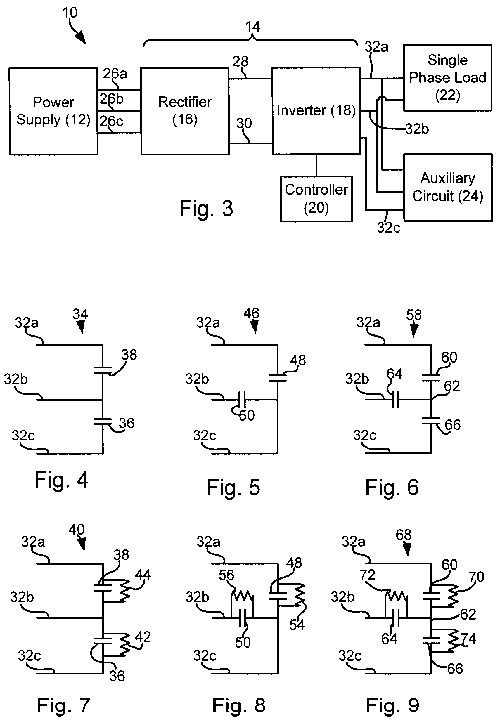
[0036]Referring now to FIGS. 4 and 7, in accordance with the invention, an auxiliary circuit 34 includes an auxiliary capacitor 36 connected to lines 32b and 32c. Auxiliary circuit 34 can further include a filter capacitor 38 connected to lines 32a and 32b (the same lines to which the single-phase load is connected). Auxiliary capacitor 36 and filter capacitor 38 may be paralleled with damping resistors 42 and 44 to form an auxiliary circuit 40 (see FIG. 7). Auxiliary circuits 34 and 40 are configured to compensate for single-phase load 22 driven by three-phase drive system 10 (as shown in FIG. 3). Capacitors 36 and 38 can be sized and configured to smooth out the PWM current generated by three-phase current source inverter 18. Damping resistors 42 and 44 can be sized and configured so as to dampen any unwanted harmonics and / or oscillations. The determination and calculation of the sizing of capacitors 36 and 38 will be discussed hereinafter.

[0037]Auxiliary circuit 34 can be designe...

second embodiment

[0063]Referring now to FIG. 5, in accordance with the invention, an auxiliary circuit 46 includes a first auxiliary capacitor 48 connected to supply lines 32a and 32c, and a second auxiliary capacitor 50 connected to supply lines 32b and 32c. As discussed hereinabove, single-phase load 22 is connected between supply lines 32a and 32b. First and second auxiliary capacitors 48 and 50 can be paralleled with damping resistors to form an auxiliary circuit 52 as shown in FIG. 8. Auxiliary circuit 52 includes a first auxiliary capacitor 48 and a parallel resistor 54 connected between supply lines 32a and 32c, and a second auxiliary capacitor 50 and a parallel resistor 56 connected between supply lines 32b and 32c. Design and sizing of first and second auxiliary capacitors 48 and 50 will be discussed hereinafter. Damping resistors 54 and 56 can be sized and configured so as to dampen any unwanted harmonics and / or oscillations.

third embodiment

[0064]Referring now to FIG. 6, in accordance with the invention, an auxiliary circuit 58 includes a first auxiliary capacitor 60 connected between supply line 32a and an auxiliary line 62, a second auxiliary capacitor 64 connected between supply line 32b and auxiliary line 62 and a third auxiliary capacitor 66 connected between supply line 32c and auxiliary line 62. As discussed hereinabove, single-phase load 22 is connected between supply lines 32a and 32b. Auxiliary capacitors 60, 64, and 66 can be paralleled with damping resistors 70, 72, and 74, respectively, to form an auxiliary circuit 68 as illustrated in FIG. 9. Design and sizing of the first, second and third auxiliary capacitors 60, 64, and 66 will be discussed hereinafter. Damping resistors 70, 72 and 74 can be sized and configured so as to dampen any unwanted harmonics and / or oscillations.

[0065]The design and sizing of auxiliary circuit 58 can be simplified similarly to the design and sizing of auxiliary circuit 34 by an...


PUM


Abstract

An auxiliary circuit for reducing low order current harmonics in a three-phase drive system driving a single-phase load, the three-phase drive system including a three-phase source voltage connected to a rectifier system connected to a DC link choke inductor connected to a three-phase current source inverter system.

Description

CROSS-REFERENCE TO RELATED APPLICATIONS[0001]This application claims the benefit of U.S. Provisional application 60 / 704,614 filed Aug. 2, 2005, hereby incorporated by reference.STATEMENT REGARDING FEDERALLY SPONSORED RESEARCH OR DEVELOPMENT[0002]Not applicable.BACKGROUND OF THE INVENTION[0003]The present invention relates generally to power conversion and conditioning and, more particularly, to an auxiliary circuit for reducing current harmonics from an unbalanced load.[0004]Power plants are linked to power consuming facilities (e.g., buildings, factories) via utility grids designed so as to be extremely efficient in delivering massive amounts of power. To facilitate efficient distribution, power is delivered over long distances as low frequency three-phase AC current.[0005]Despite being distributable efficiently, low frequency AC current is sometimes not suitable for end use in consuming facilities. Thus, prior to end use, power delivered by a utility has to be converted to a useab...

Claims


Application Information

Patent Timeline
Patent Type & Authority Patents(United States)
IPC IPC(8): H02M1/12H02M7/00
CPCH02M1/126H02M5/4585
Inventor WEI, LIXIANGSKIBINSKI, GARY L.LUKASZEWSKI, RICHARD A.
Owner ROCKWELL AUTOMATION TECH
Why Eureka
Try Eureka