System and method for monitoring and managing electrical power transmission and distribution networks

Inactive Publication Date: 2009-04-14
APLICACIONES & INFORMATICA AVANZADA
View PDF13 Cites 47 Cited by
  • Summary
  • Abstract
  • Description
  • Claims
  • Application Information

AI Technical Summary

Benefits of technology

[0045]Disclosed herein is a deterministic non-iterative method that improves the existing methods to solve the load flow equations of any power system. Such method in turn provides improved methods for state estimation, generation of restoration plans, the construction of PV and QV curves, voltage stability and contingency analysis, optimal power flow, and operation limits control.

Problems solved by technology

The global electric industry is facing a number of challenges: an aging infrastructure, growing demand, and rapidly changing markets, all of which threaten to reduce the reliability of the electricity supply.
Increasing demand due to economic and demographic variations, without additional generation investments, has led transmission and distribution systems worldwide to their limits of reliable operation.
According to the North American Electric Reliability Council (NAERC), transmission congestion is expected to continue over the next decade.
Yet, even this important step towards nationwide coordination raises concerns about transmission reliability.
In its report, “Reliability Assessment 2001-2010,” the NAERC stated, “The transition period from existing grid operation arrangements to the new world of RTO-managed grids may create some negative system reliability impacts.
One specific type of transmission system voltage instability is the slow spreading uncontrollable decline in voltage known as voltage collapse.
From a momentary interruption to a full blackout, any disturbance is costly to the provider and consumers alike.
The rest of the solutions are spurious and cannot represent the physical solution of a real power system.
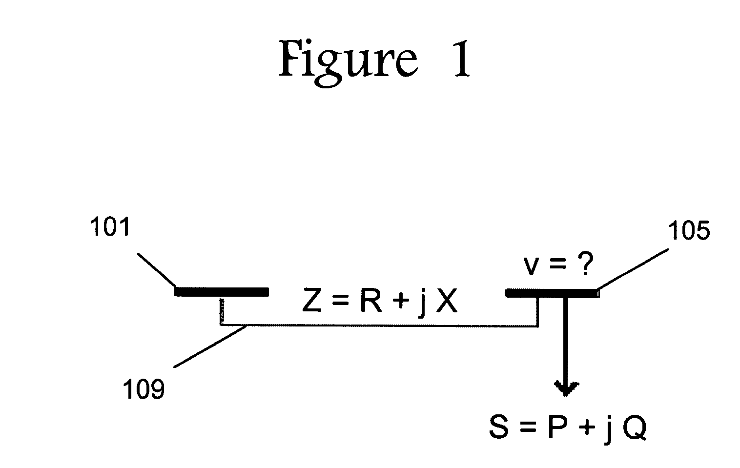
A power system model with a complete set of exact measurements for all parameters is not possible; hence, observation of real values is limited to a subset of all needed parameters.
This methodology presents two majors drawbacks:a) Even in the case where there is a solution, FDNR may not be able to find it, due to the fractal nature of the convergence region of this algorithm.
This is inherent to the iterative nature of the Newton-Raphson Methodology.b) FDNR cannot assure that a solution (one that solves the mathematical equations) really represents the physical one.
The problems of the FDNR methodology are well known by the electrical sector, taking the form of stochastic non-convergence or dependency of the result in the order of the actions over the network.
Several attempts to overcome these difficulties have been undertaken in the past, but with limited success.
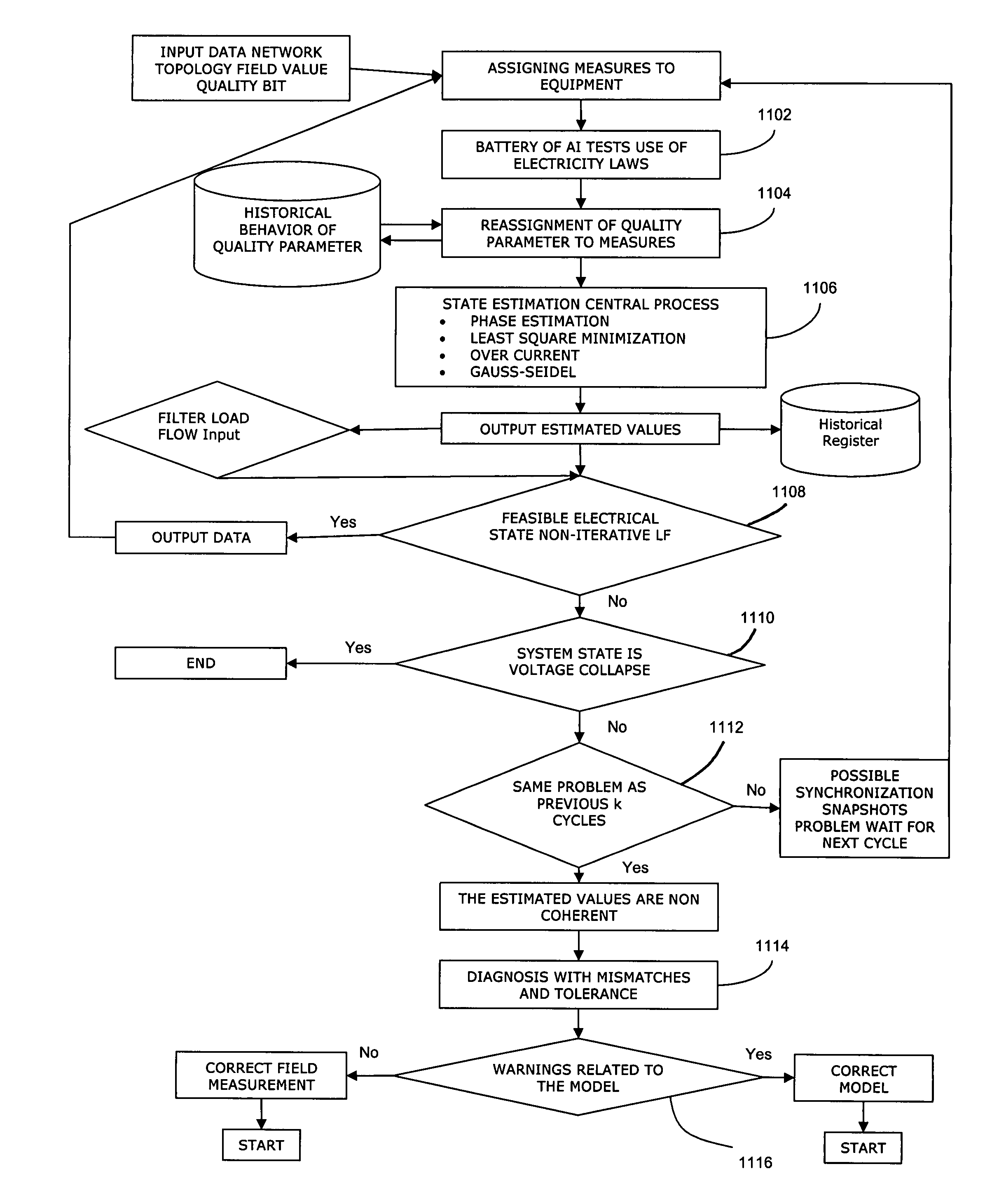
1) Limit violation control of parameters outside operating limits. These processes may comprise intelligent methods that generate proposed remedial actions by means of using load flow on the last estimated snapshot or state of the power system by the EMS State Estimator automatically (by means of an algorithm) or manually using a real time network simulation by the operator. Some physical devices, such as protections and others with or without local intelligence, have also been developed as alternatives, including U.S. Pat. No. 5,428,494 to Ahuja, which presents a system for over-voltage and under-current protection, and U.S. Pat. No. 5,327,355 to Chiba et al., which presents a fuzzy logic based method for tap transformer settings for voltage control. Extreme remedial action always involve load shedding, which process is treated in some form in U.S. Pat. No. 4,324,987 to Sullivan, II et al., U.S. Pat. No. 4,337,401 to Olson, U.S. Pat. No. 4,583,182 to Breddan, and U.S. Pat. No. 5,414,640 to Seem. A method for controlling voltage and reactive power fluctuations in adjacent power systems is discussed in U.S. Pat. No. 6,188,205 to Tanimoto et al.
2) Planned maintenance outages assessment through instant real time on line simulation from the actual network state.
3) Optimal power flow for objective functions such as losses minimization through reactive power cycling.
4) Voltage stability analysis, which can be viewed as the aggregation of the following:a. PV and QV curves construction.b. Determination of voltage collapse point and current operating point as well as voltage stability criterion.c. Generating a metric to voltage collapse. One such example is the margin to voltage collapse defined as the largest load change that the power system may sustain at a set of buses from a well-defined operating point, as described in U.S. Pat. No. 5,745,368 to Ejebe et al.d. Voltage stability assessment and contingency analysis and classification. Concerning voltage stability security assessment, state of the art load flow methodologies in general do not work. A well detailed explanation on which of these tasks they tend to fail can be found on U.S. Pat. Nos. 5,594,659 and 5,610,834 to Schlueter. Because of this, Newton-Raphson is ill conditioned for the situation. In the cited patents, Schlueter states that current methods lack diagnosis procedures for determining causes of specific voltage instability problems, as well as intelligent preventive procedures. His method is an attempt to overcome this situation in certain cases. He provides for detecting if certain contingencies (line outages and loss of generation) related to reactive reserve basins can cause voltage instability.
With ageing infrastructures and growing demand, disturbances are increasingly likely to happen.
Traditionally, restoration after a disturbance has been one of the most difficult things for electrical companies to handle.
While hundreds of hours of systems analysis and documentation go into restoration plans, they never match the reality of any specific disturbance, and they are dynamic in nature.
This last aspect is responsible for not being able to behave well when disruptions of the system state take place, when a major disturbance or blackout takes place.
To conclude, we add that when the electrical network state is close to voltage collapse, precisely when operators and planners need the support of these tools the most, traditional methods fail and frequently cannot deliver a correct calculation.

Method used


Image

  • System and method for monitoring and managing electrical power transmission and distribution networks
  • System and method for monitoring and managing electrical power transmission and distribution networks
  • System and method for monitoring and managing electrical power transmission and distribution networks

Examples


Embodiment Construction

[0055]To illustrate the well-known fact of the ill condition of the existing state of the art methodology in the vicinity of voltage collapse, we will use a very simple example of a very small network with final quadratic load flow equations (exact solutions are easily computed).

[0056]Referring to FIG. 1, the general load flow problem has at least one swing node 101 and a set of nodes (generation and / or load). In the very simple minimalist example chosen, we will only have one node 105 as well as the swing node 101. This swing node 101 does not vary its voltage value no matter how load and topology may vary in the rest of the network. It acts as a large generator or substation capable of providing any power required by the system. Only active power and reactive power are calculated at the swing bus, balancing the sum of both at the rest of the nodes.

[0057]An alternate current in stationary regime satisfies Ohms law with complex values. This is the origin of the complex values (X ind...


PUM


Abstract

A system and method for monitoring and managing electrical power transmission and distribution networks through use of a deterministic, non-iterative method using an holomorphic embedding and algebraic approximants for determining the real-time load flow in a power generating system having an electrical grid. Such method may be employed for real-time or off-line applications for electric power systems reliability assessment, and is capable of determining whether or not a physical solution to the load flow problem exists, or if the system is in a state of voltage collapse.

Description

CROSS-REFERENCE TO RELATED APPLICATIONS[0001]This application is a continuation-in-part of and co-owned U.S. patent application Ser. No. 10 / 702,293 entitled “System and Method for Monitoring and Managing Electrical Power Transmission and Distribution Networks”, filed with the U.S. Patent and Trademark Office on Nov. 6, 2003 now abandoned, by the inventor herein, which is based upon and claims benefit of copending and co-owned U.S. Provisional Patent Application Ser. No. 60 / 424,351 entitled “Method and System for Monitoring and Managing Electrical Power Transmission and Distribution Networks”, filed with the U.S. Patent and Trademark Office on Nov. 6, 2002, by the inventor herein, the specifications of which are incorporated herein by reference.BACKGROUND OF THE INVENTION[0002]1. Field of the Invention[0003]The present invention relates to monitoring and management of electrical power transmission and distribution networks, and more particularly to a system and method for determining...

Claims


Application Information

Patent Timeline
Patent Type & Authority Patents(United States)
IPC IPC(8): G06F11/30G06F19/00H02J3/00
CPCH02J3/00H02J2003/007Y04S40/22Y02E60/76G01R19/2513H02J2203/20Y02B70/3225Y02E60/00Y04S20/222Y04S40/20G01R21/00G01R35/00
Inventor TRIAS, ANTONIO
Owner APLICACIONES & INFORMATICA AVANZADA
Why Eureka
Try Eureka