
Gas chromatograph
a gas chromatograph and chromatograph technology, applied in the field of gas chromatographs, can solve the problems of reduced separation, false positive identification, and unsuitable for fast real-time monitoring, and achieve the effect of improving the chemical separation power of chemical detectors and excellently solving problems
Patent Information
- Authority / Receiving Office
- US · United States
- Patent Type
- Patents(United States)
- Current Assignee / Owner
- Publication Date
- 2009-04-21
- Estimated Expiration
- Not applicable · inactive patent
Smart Images

Figure 1 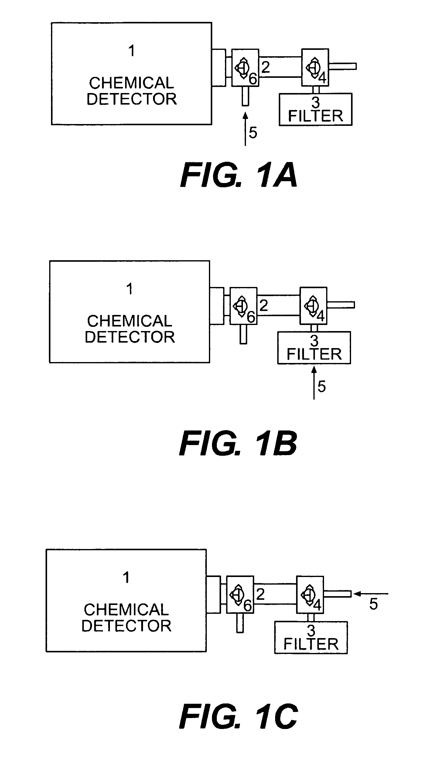
Figure 2 
Figure 3
Abstract
Description
FIELD OF THE INVENTION
[0001] The invention relates to a gas chromatograph for the analysis of a sample, having a feed arrangement for feeding the sample, an open tubular capillary column for separating the components of the sample, temperature control means for controlling the temperature of the column, and a detector for detecting the separated components of the sample, wherein said column comprises a bundle of open tubular capillaries.BACKGROUND
[0002] The chemical state of a gas phase sample is formed by vaporized or gaseous chemical species mixed with an ambient medium, typically environmental air. Instead of air, the medium can be process gases or vacuum. The detector is used to detect and identify defined chemical species in the defined surrounding media.
[0003] Characteristic for a chemical detector is its capability to convert a chemical state to an electrical signal and transmit the signal for further processing. Typically it is aimed at performing both qualitative and quantitat...
Examples
examples
[0048]The following examples illustrate, but do not limit, the basic features of the present invention.
[0049]The arrangement is similar as those presented in FIG. 1 and FIG. 2. The bundle of hollow fiber membrane capillaries originates from a membrane dryer (Drypoint Beko). The detector is ChemPro100 (Environics) using 1 l / min flow rate.
[0050]The zero time (retention time=0) is determined by switching the valve (4) from the position shown in FIG. 1 (b) to the position shown in FIG. 1 (c).
[0051]FIG. 3 shows a result of feeding mixtures of methyl salicylate (MeS) and di-isopropyl methyl phosphonate (DIMP) (1% DIMP and 99% MeS) through a bundle of hollow fiber membranes to the detector.
[0052]The detector sucks air through a filter and measure a clean background signal. The valve (4) was switched to the position shown in FIG. 1 (c) and the sample was introduced at the same time. After three seconds the valve 4 was switched to the position shown in FIG. 1 (b). This procedure introduces a...