

Steering apparatus for vehicle
a technology for steering apparatuses and vehicles, applied in vessel construction, steering initiations, instruments, etc., can solve problems such as the inability to adjust automatically, and achieve the effect of reducing steering load and more accurate steering angle control
- Summary
- Abstract
- Description
- Claims
- Application Information
AI Technical Summary
Benefits of technology
Problems solved by technology
Method used
Image

Examples
first embodiment
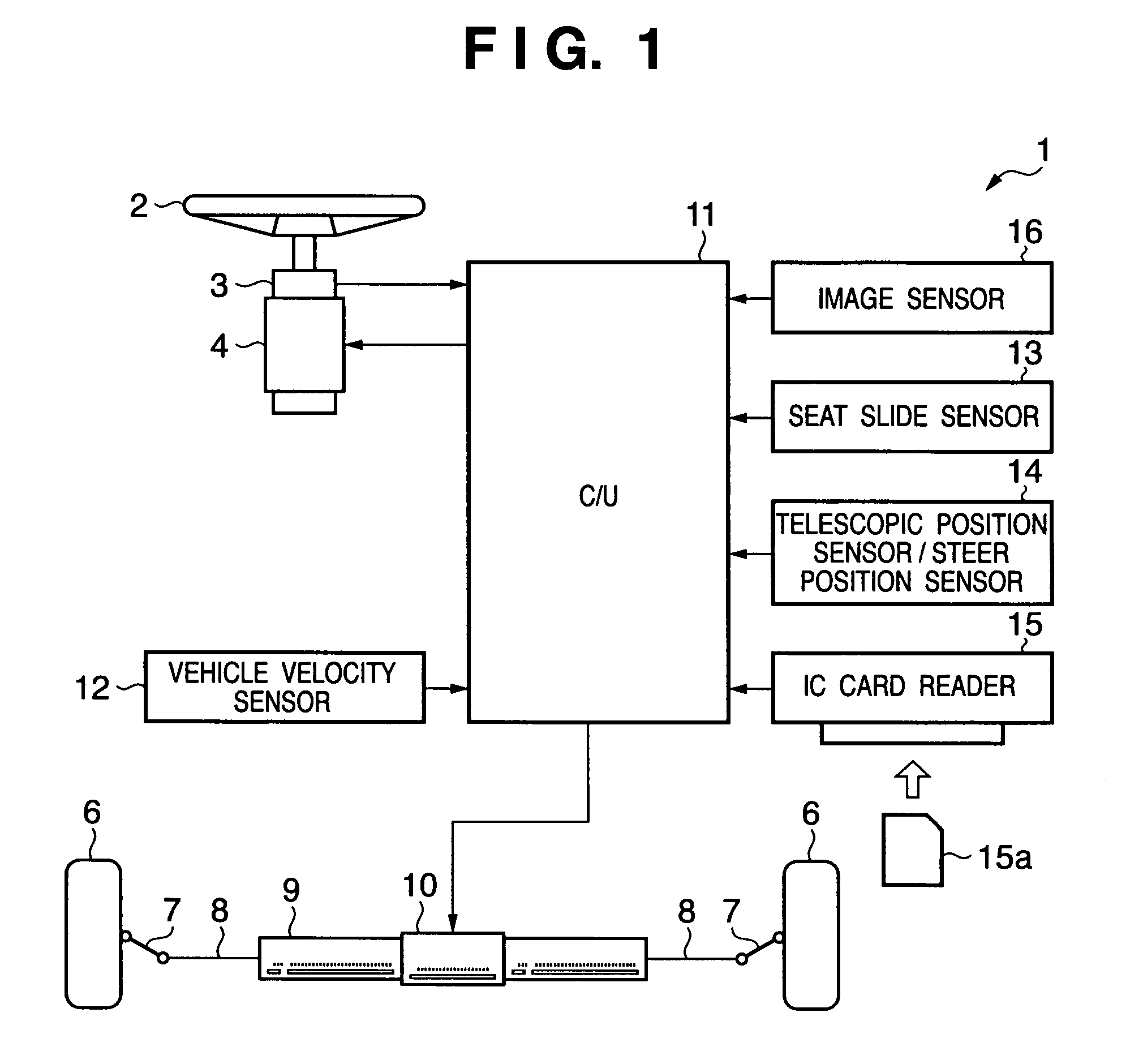
[0107]FIG. 1 is a schematic diagram showing the arrangement of a steering apparatus 1 according to this embodiment.
[0108]Referring to FIG. 1, reference numeral 2 denotes a steering wheel. To this steering wheel 2, a steering angle sensor 3 for detecting the steering angle of the steering wheel 2, and a steering reaction force generation motor 4 are attached.
[0109]A pair of right and left tires 6 are coupled via knuckle arms 7, tie rods 8, and a steering rod 9, and a steering motor 10 for driving the steering rod 9 in the axial direction to give a steering angle to the tires 6 is provided at the center of the steering rod 9.
[0110]The steering apparatus 1 shown in FIG. 1 is of a so-called steer-by-wire type. That is, the steering rod 9 is not mechanically connected to the steering wheel 2 via a steering shaft or the like but is electrically connected to it. A control unit (C / U) 11 executes steering control of the steering wheel 2 via such electrical connection. A detection value (corr...
second embodiment
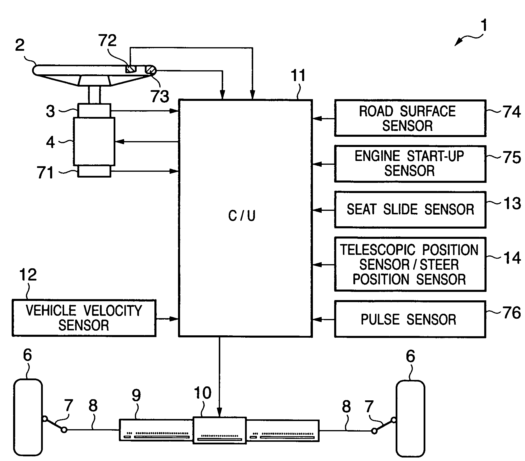
[0140]FIG. 7 is a schematic diagram showing the arrangement of the steering apparatus 1 of this embodiment. This steering apparatus 1 is of the steer-by-wire type as in FIG. 1. The same reference numerals in FIG. 7 denote the same components as those in FIG. 1, and a description thereof will be omitted. Components different from FIG. 1 will be described below.
[0141]A steering torque sensor 71 is attached to the steering wheel 2, and a pressure sensor 72 which detects the gripping state of the steering wheel by the driver, and an electrostatic sensor 73 which determines the gripping position of the steering wheel based on a change in capacitance are provided.
[0142]In addition, the steering apparatus 1 of this embodiment has a road surface sensor 74 which detects a low-μ road and road surface drop, an engine start-up sensor 75 which detects engine start-up, and a pulse sensor 76 which detects the tension level of the driver. When the vehicle is a so-called hybrid vehicle which uses an...
third embodiment
[0198]The third embodiment is a variation of the aforementioned second embodiment. FIG. 10A shows the example of the measurement signal, and this measurement signal may be corrected according to a situation.
[0199]For example, upon generating the measurement signal in step S2022 in FIG. 9, the travel state of the vehicle is detected, and the measurement signal is corrected according to the detected travel state. More specifically, it is desirable to correct the measurement signal to have a larger amplitude in the following travel state:[0200](a) when the road surface μ detected by the road surface sensor 74 is lower than a predetermined value;[0201](b) when the steering angle detected by the steering angle sensor 3 is larger than a predetermined value during a steady turn or after an elapse of a predetermined period of time in continuous travel; or[0202](c) when the vehicle velocity detected by the vehicle velocity sensor 12 exceeds a predetermined value.
[0203]It is considered that t...
PUM
 Abstract
Description
Claims
Application Information