Fluid applying apparatus

a technology of fluid application apparatus and nozzle, which is applied in the manufacture of electrode systems, discharge tube coatings, instruments, etc., can solve the problems of increased manufacturing costs, difficult to obtain constant filling amount over the entire front/back-face plate, and large-scale screen printing plate. achieve the effect of reducing the fluid pressure of the pump chamber

Inactive Publication Date: 2009-04-21
PANASONIC CORP
View PDF13 Cites 3 Cited by
  • Summary
  • Abstract
  • Description
  • Claims
  • Application Information

AI Technical Summary

Benefits of technology

[0024]a moving-member driving device for driving the moving member to make the housing perform the rotational motion or the rectilinear motion so that applying-fluid pressure inside the pump chamber is increased or reduced;
[0033]the moving-member driving device is a piston-axis-direction driving device for driving the piston into the rectilinear motion within the housing, thereby increasing and decreasing the pump chamber defined between the piston and the housing, whereby the fluid pressure inside the pump chamber is increased or decreased.
[0053]According to a 16th aspect of the present invention, there is provided the fluid applying method according to the 12th aspect, wherein meniscus is maintained generally identical in shape during intervals of application rest by giving both an action of making a meniscus of the applying fluid projected from the discharge port, and an action of reducing the fluid pressure of the pump chamber to suck the applying fluid through the discharge port into the pump chamber.
[0061]According to a 21st aspect of the present invention, there is provided the pattern formation method for plasma display panels according to the 20th aspect, wherein after the voltage is dropped, the pressure of the pump chamber is reduced, whereby the application line is interrupted.

Problems solved by technology

With the conventional screen printing method, a large-scale screen makes it hard to achieve high-precision alignment of the screen printing plate, and in filling the fluorescent substance materials, the materials might be placed even on the top portions of the partition walls.
Thus, it is quite hard to obtain a constant filling amount over the entire front-face plate / back-face plate.
However, this necessitates exposure and development steps, involving a number of steps larger than that of the screen printing method, giving rise to an issue of increased manufacturing cost.
However, this method is, at the present stage, capable of treating only low-viscosity fluids of about 10 mPa·s and incapable of managing high-viscosity fluids from the driving method and structural constraints.
Further, the powder diameter that can be prevented from clogging of the flow passage is limited to about 0.1 μm, posing large constraints in terms of material.
However, also in this case, because the ink jet method is only capable of treating a low-viscosity nanopaste, the drawing lines would result in smaller thicknesses, causing the wiring resistance to become high.
As a result, overstrikes would be required to ensure the thickness, posing an issue in terms of production cycle time.
However, this electric-field jet method has had the following issues.
① Poor stability of application flow rate; and
The above ② is due to poor responsivity of the air type dispenser.
However, with the use of the pressurization device 508 using air pressure for obtainment of larger application flow rates, starting and terminating ends of the continuous application line cannot be drawn at high grade because of the poor response of the air type.
Otherwise, at the terminating end of a drawing line, even if the air pressure is lowered simultaneously with turn-off of the voltage at a start of application, the air pressure cannot be immediately dropped to a specified pressure.

Method used


Image

  • Fluid applying apparatus
  • Fluid applying apparatus
  • Fluid applying apparatus

Examples


first embodiment

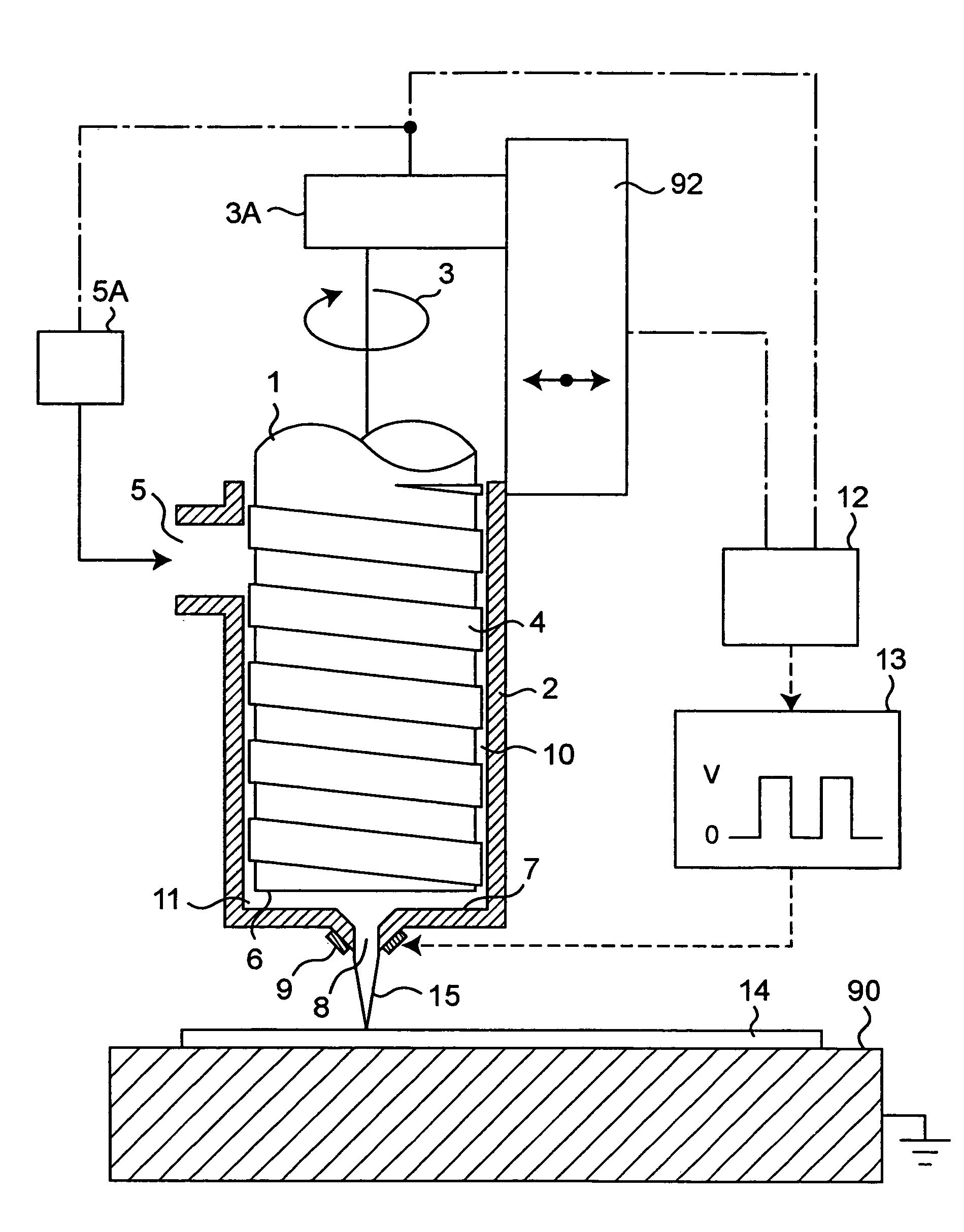
[0102]FIG. 1 is a partial cross-sectional schematic view for explaining a fluid applying apparatus capable of embodying a fluid applying method according to a first embodiment of the present invention.

[0103]Reference numeral 1 denotes a piston, and 2 denotes a housing for housing this piston 1 therein. In the case where the applying material can be treated as a nonconductive one, the housing 2 may be made of either an insulative material or a conductive material. When a conductive material is used for the whole housing 2, the nozzle tip end, which is the closest to the substrate, is the highest in electric field strength, so that the function of electric field control has no obstacles. However, when it is not desirable to apply high voltage to the whole housing 2 in terms of safety, a concrete example is shown in FIG. 29, it is appropriate to use an insulative material only for a discharge portion (364 in FIG. 29) where the electrode is to be provided, and to use a conductive materi...

third embodiment

[0125]FIGS. 4A and 4B are partly cross-sectional schematic views for explaining a fluid applying apparatus capable of carrying out a fluid applying method according to a third embodiment of the present invention, showing a case where a thrust dynamic seal is used as another example of the device for generating the suction force f2 of tending to return to the interior of the discharge nozzle. The piston shaft of a dispenser used in the fluid applying apparatus and method according to this third embodiment, like the fluid applying apparatus and method according to the second embodiment, is so structured that the piston shaft is enabled to make rectilinear motion simultaneously with rotational motion by a two-degree-of-freedom actuator (more specifically, rotation transmission device 603A and axial-direction movement device 604A). A thrust dynamic seal is formed between a discharge-side end face of the piston shaft and its opposing surface.

[0126]Reference numeral 601 denotes a piston h...

fourth embodiment

[0129]FIG. 5A is a partly cross-sectional schematic view showing a fluid applying apparatus capable of carrying out a fluid applying method according to a fourth embodiment of the present invention, showing a case where a counter electrode (hereinafter, referred to as space electrode) is placed in a space between the discharge nozzle and the substrate without making use of the substrate as a counter electrode. That is, a voltage is applied to between the housing-side electrode, which is placed in part or entirety of the housing (dispenser), and the space electrode, by which an electric field is formed. With this constitution, there is no need for forming a conductive film on the substrate side or placing a conductive-substance plate material or the like under the substrate, so that restrictions on application objects can be eliminated. This produces an advantage for drawing ultrafine lines even in the case of, for example, a thick substrate because a large electric field strength ca...


PUM

PropertyMeasurementUnit
diameteraaaaaaaaaa
viscosityaaaaaaaaaa
diameteraaaaaaaaaa

Abstract

A meniscus of applying fluid is controlled by applying a voltage to a discharge-nozzle side electrode and a counter electrode placed downstream of the discharge nozzle and by increasing or decreasing fluid pressure inside a pump chamber with use of a mechanism for rotational motion or rectilinear motion.

Description

BACKGROUND OF THE INVENTION[0001]The present invention relates to very small-flow-range fluid applying apparatus and fluid applying method required in such fields as information / precision equipment, machine tools, and FA (Factory Automation); or in various production processes of semiconductors, liquid crystals, displays, surface mounting, and the like, and also relates to a plasma display panel formed by the fluid applying method and a pattern formation method therefor.[0002]Issues related to conventional printing techniques are explained below by taking as an example a technique for forming the fluorescent substance layer of plasma display panels (hereinafter, referred to as PDPs).[0003]A PDP that performs color display has, on its front-face plate / rear-face plate, a fluorescent substance layer composed of fluorescent substance materials that emit light in RGB (red, green, blue) colors, respectively. This fluorescent substance layer is so structured that three stripes which are fi...

Claims


Application Information

Patent Timeline
Patent Type & Authority Patents(United States)
IPC IPC(8): B05C5/00B05D1/04B05C5/02B05C11/10B05D1/26B05D7/00B05D7/24H01J9/02H01J9/227H01J11/10H01J17/49
CPCB05C5/02B05C11/10H01J9/02H01J11/10H01J2209/015H01J11/12
Inventor MARUYAMA, TERUOSONODA, TAKASHITAKII, YOSHIMASA
Owner PANASONIC CORP
Why Eureka
Try Eureka