Trench semiconductor device of improved voltage strength, and method of fabrication

a semiconductor device and trench technology, applied in the field of trench semiconductor devices of improved voltage strength and method of fabrication, can solve the problems of undesired impurity diffusion from one part, unnecessarily wide deep guard rings, failure in field concentration mitigation, etc., and achieve the effect of improving the voltage-withstanding capability of trench semiconductor devices

Inactive Publication Date: 2009-04-21
SANKEN ELECTRIC CO LTD
View PDF2 Cites 13 Cited by
  • Summary
  • Abstract
  • Description
  • Claims
  • Application Information

AI Technical Summary

Benefits of technology

[0010]The present invention has it as an object to improve the voltage-withstanding capability of trench semiconductor devices without relying on the creation of guard trenches to overly stringent dimensional and positional specifications.
[0014]Thus the capacitive coupling conductors may be appropriately patterned for optimizing the associated capacitive couplings, hence the potentials of the guard trench conductors, and hence the contour of the depletion layer in the neighborhood of the guard trenches. The optimum contouring of the depletion layer is far easier with the capacitive coupling conductors of this invention than without them, because, by virtue of the method of this invention outlined above, the capacitive coupling conductors can be made to much more strict dimensional and positional specifications than the guard trenches. Trench semiconductor devices that can withstand target voltages may therefore be made more easily than heretofore.

Problems solved by technology

However, being created by diffusion of a conductivity type determinant into the semiconductor substrate, such deep guard rings become unnecessarily wide as a result of inevitable lateral, in addition to desired depth-wise, diffusion of the conductivity type determinant.
The depletion layer is not formed in some such spacings, with a consequent failure in mitigation of field concentrations.
Third, the fabrication of guard rings by impurity diffusion necessitates the semiconductor substrate to be held at high temperatures for prolonged lengths of time.
Such prolonged heating of the semiconductor substrate brings about an undesired impurity diffusion from one part to another of the substrate.
An undesired impurity diffusion will occur from n-type buffer region to n−-type base region of the IGBT, to such an extent that the latter region will become unnecessarily high in impurity concentration.
The base region with such high impurity concentration will make it difficult for the depletion layer to spread therethrough.
The device will then fail to withstand as high voltages as desired.
Despite all these advantages over the guard rings, the guard trenches as hitherto created possessed some difficulties left unremedied.
Currently, however, there exist limitations that are still insurmountable for fabricating guard trenches to sufficiently close tolerances to provide such rugged semiconductor devices.

Method used


Image

  • Trench semiconductor device of improved voltage strength, and method of fabrication
  • Trench semiconductor device of improved voltage strength, and method of fabrication
  • Trench semiconductor device of improved voltage strength, and method of fabrication

Examples


embodiment

of FIG. 7

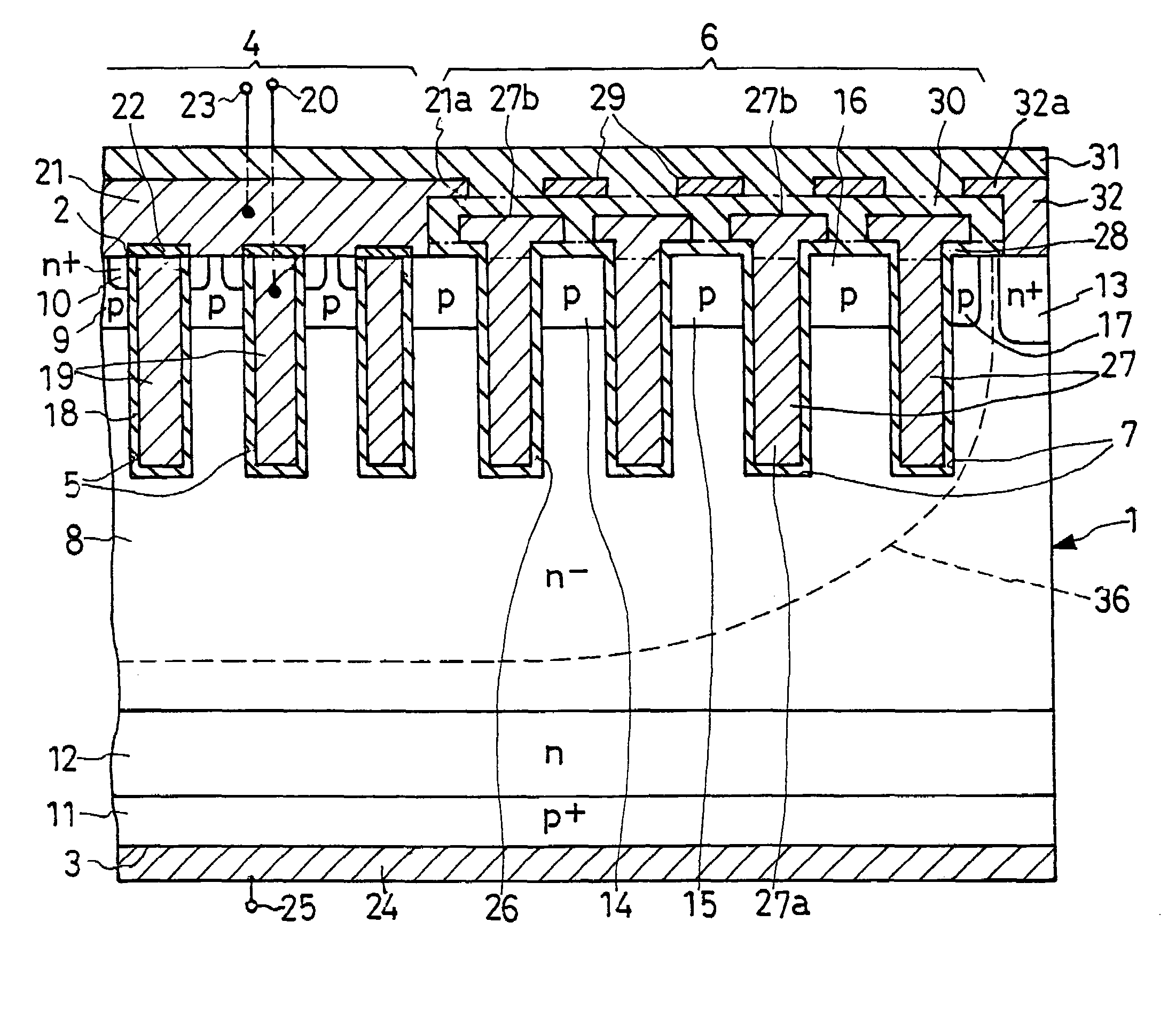
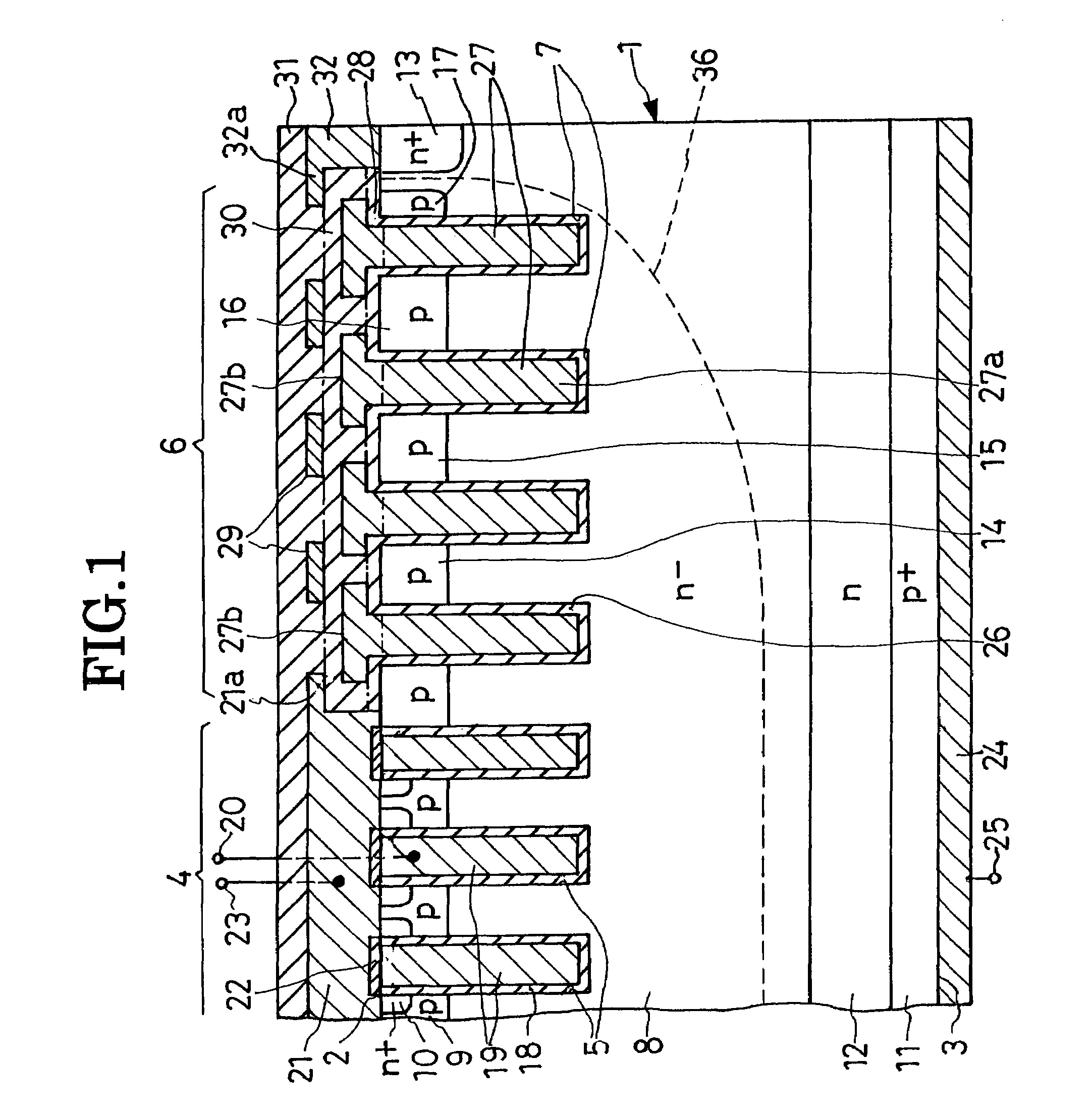
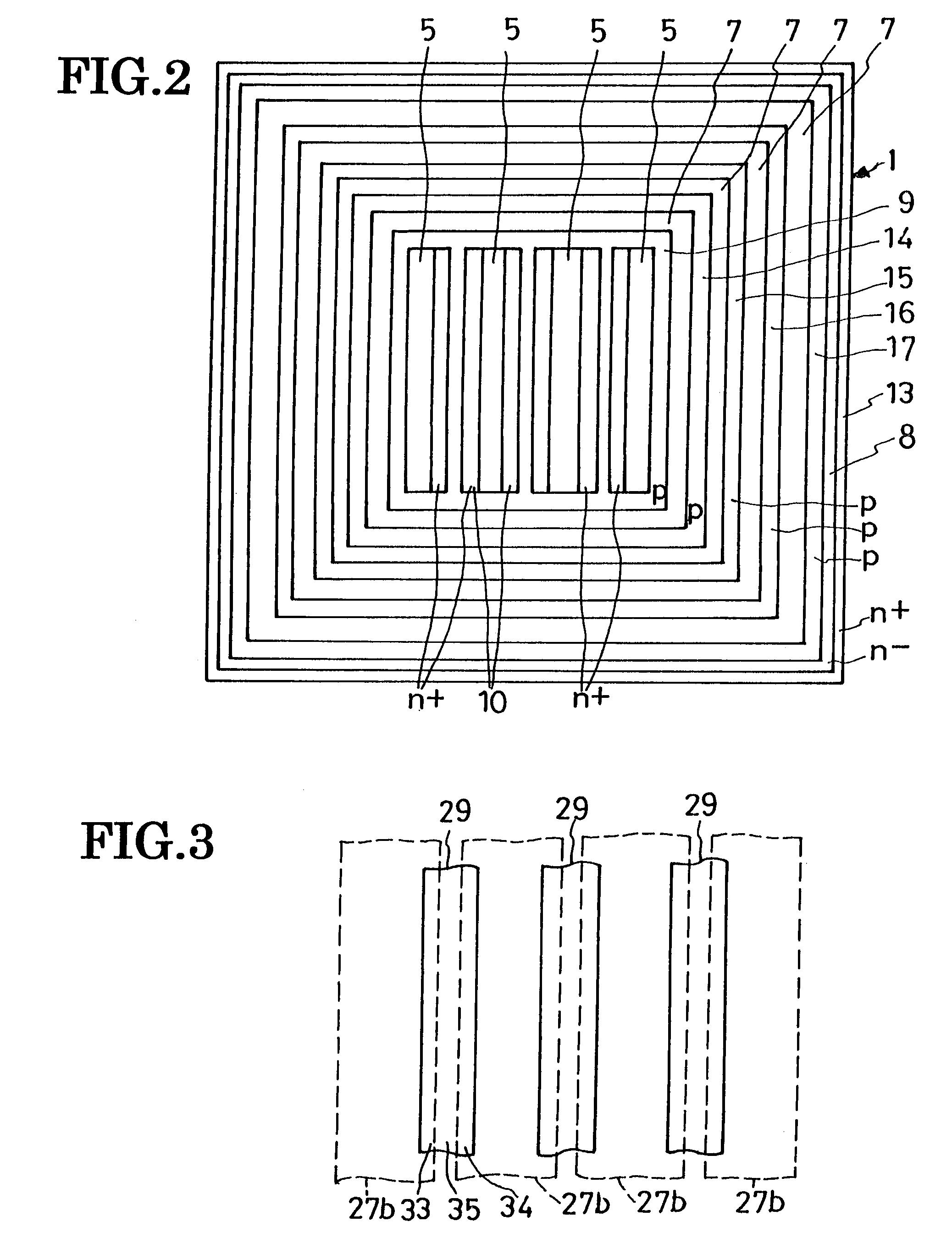
[0082]The IGBT shown here features modified cell trenches 5a, modified p-type base region 9a, and modified n+-type emitter regions 10a and is otherwise similar in construction to that of FIGS. 1-6. The cell trenches 5a are formed centrally in the semiconductor substrate 1 in latticelike arrangement, bounding islandlike n+-type emitter regions 10a in an array. The p-type base region 9a is exposed in part centrally in each emitter region 10a and in part between the latticed cell trenches 5a and the inmost annular guard trench 7.

[0083]It is understood that the cell trenches 5a receive cell trench conductors via cell trench insulators, and the guard trenches 7 receive the guard trench conductors via the guard trench insulators. Thus the second preferred form of IGBT offers the same benefits as the first.

Embodiment of FIG. 8

[0084]Another preferred form of IGBT according to the invention has a latticelike p-type base region 9b defining an array of islandlike n+-type emitter regio...


PUM


Abstract

A trench IGBT is disclosed which includes a semiconductor substrate having formed therein a set of cell trenches formed centrally and a set of annular guard trenches concentrically surrounding the cell trenches. The cell trenches receive cell trench conductors via cell trench insulators for providing IGBT cells. The guard trenches receive guard trench conductors via guard trench insulators for enabling the IGBT to withstand higher voltages through mitigation of field concentrations. Capacitive coupling conductors overlie the guard trench conductors via a dielectric layer, each for capacitively coupling together two neighboring ones of the guard trench conductors. The capacitive coupling conductors are easily adjustably variable in shape, size and placement relative to the guard trench conductors for causing the individual guard trench conductors to possess potentials for an optimal contour of the depletion layer.

Description

CROSS REFERENCE TO RELATED APPLICATIONS[0001]This application claims priority to Japanese Patent Application No. 2005-245533, filed Aug. 26, 2005.BACKGROUND OF THE INVENTION[0002]This invention relates to semiconductor devices as typified by insulated gate bipolar transistors (IGBTs), and particularly to those having guard trenches, in addition to cell trenches, etched into the semiconductor substrate for higher voltage strength. The invention also specifically pertains to a method of fabricating such trench semiconductor devices.[0003]IGBTs have been known which are cell-trenched to withstand higher voltages, as disclosed for example in Japanese Unexamined Patent Publication No. 9-283754. The cell trenches accommodate gate electrodes via insulators.[0004]The same unexamined patent application also teaches how to improve the voltage strength of the IGBT at the periphery of the semiconductor substrate around the group of IGBT trench cells placed centrally thereon. Employed to this en...

Claims


Application Information

Patent Timeline
Patent Type & Authority Patents(United States)
IPC IPC(8): H01L29/94H01L21/336
CPCH01L29/0696H01L29/404H01L29/407H01L29/7397H01L29/73
Inventor TAKAHASHI, TETSUYA
Owner SANKEN ELECTRIC CO LTD
Why Eureka
Try Eureka