Real-time linear-birefringence-detecting polarization microscope

a polarizing microscope and real-time technology, applied in the field of detecting and displaying indications of linear birefringence in polarizing microscope images, can solve the problems of complex observed effects that were formerly difficult to analyze, current polarizing microscopy techniques rely on relatively complex hardware, and are too slow, cumbersome, and expensive for use in real-time biological sample imaging, and other uses, to achieve high-efficiency image capture

Active Publication Date: 2009-04-21
UNIV OF WASHINGTON
View PDF4 Cites 7 Cited by
  • Summary
  • Abstract
  • Description
  • Claims
  • Application Information

AI Technical Summary

Problems solved by technology

Often, two or more of these phenomena are convolved in light propagating through various media, producing complex observed effects that were formerly difficult to analyze.
Unfortunately, current polarizing microscopy techniques rely on relatively complex hardware involving mechanical rotation of samples and / or polarizers as well as on relatively intensive computational analysis of multiple captured images in order to produce a final image that indicates the presence or absence of an LB signal at discrete locations within the image.
These methods are currently too slow, cumbersome, and expensive for use in automated detection of crystals, real-time biological-sample imaging, and many other uses.

Method used


Image

  • Real-time linear-birefringence-detecting polarization microscope
  • Real-time linear-birefringence-detecting polarization microscope
  • Real-time linear-birefringence-detecting polarization microscope

Examples


Embodiment Construction

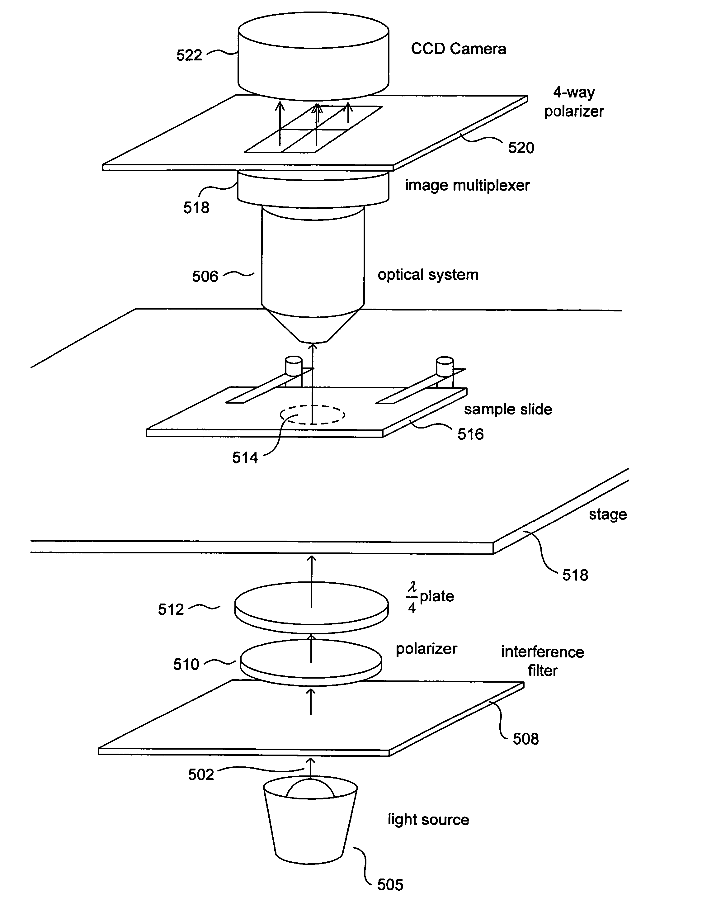
[0017]Embodiments of the present invention are directed to real-time imaging of samples by polarizing light microscopy, computation of the linear birefringence (“LB”) signal at each point in the optical image, and real-time generation and display of computed images that show the computed linear birefringence, the computed extinction angle, and the computed transmission at each point in the original, polarizing-light-microscope-generated image. In a first subsection, below, a brief overview of polarized light is provided. In a second subsection, an enhanced polarizing, optical microscope that represents one embodiment of the present invention is discussed. In a third subsection, an image-analysis software program that represents one embodiment of the present invention and that generates false-color images representing linear birefringence, extinction angle, and transmission at each point in the optical image is discussed.

Polarized Light

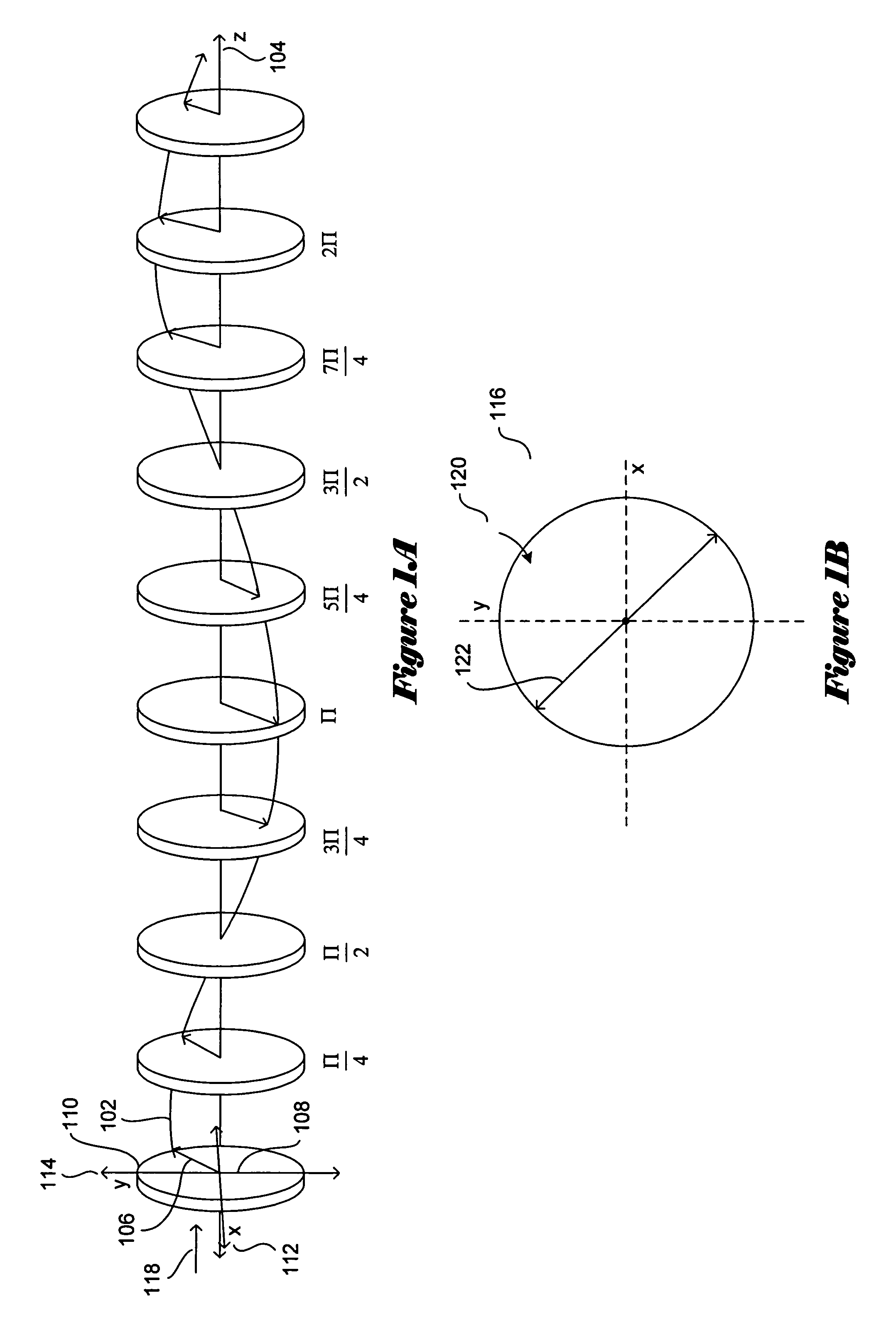
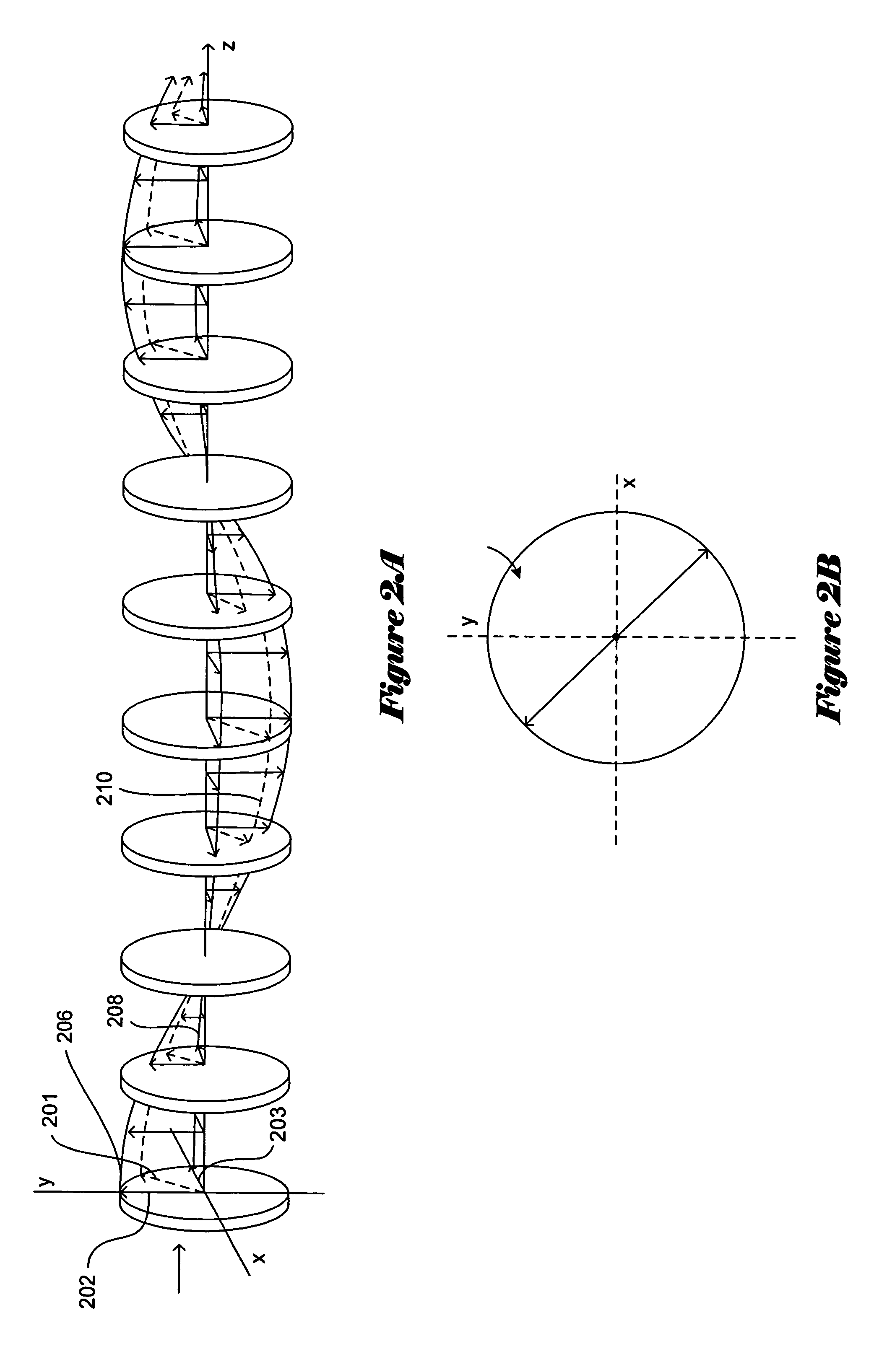
[0018]FIGS. 1A-B illustrate a simple, plain-pola...


PUM


Abstract

Various embodiments of the present invention are directed to real-time capture, analysis, and output of polarizing microscopy images that quantify detected LB signals at discrete locations within the image. In one embodiment of the present invention, circularly polarized light is passed through a sample and optically imaged by traditional polarizing-light-microscope components. The resulting image is then split four ways and analyzed by a four-way polarizer / analyzer, and the four resulting analyzed subimages are computationally processed to produce three false-color, real-time images that represent per-pixel linear birefringence, extinction angle, and transmission at each position within a quarter-sized representation of the original image produced by conventional light-microscope imaging components. The false-color images can be produced at a rate of 30 frames per second or at greater rates by employing highly efficient image capture and computational processing of captured images through efficient programming techniques.

Description

TECHNICAL FIELD[0001]The present invention is related to detecting and displaying indications of linear birefringence in polarizing microscope images and, in particular, to an enhanced polarizing microscope that captures and processes images in real time to display representations of polarization effects resulting from anisotropic refraction of circularly polarized light by optically anisotropic samples through which circularly polarized light is passed.BACKGROUND OF THE INVENTION[0002]Polarizing light microscopes have been used for approximately 200 years to study, among other things, characteristics of crystalline materials and other ordered materials. More complex instruments, referred to as “circular dichroism spectrapolarimeters,” are used to measure circular dichroism (“CD”) in optically active materials, including proteins and other biological materials. There are four different phenomena observed when plain polarized or circularly polarized light is passed through optically ...

Claims


Application Information

Patent Timeline
Patent Type & Authority Patents(United States)
IPC IPC(8): G01J4/00
CPCG01N21/6458G02B21/0004G02B21/361G02B27/286
Inventor KAMINSKY, WERNER
Owner UNIV OF WASHINGTON
Why Eureka
Try Eureka