
Photothermal conversion measurement apparatus, photothermal conversion measurement method, and sample cell

a technology of photothermal conversion and measurement apparatus, which is applied in the direction of instruments, material analysis, and withdrawal of sample devices, etc., can solve the problems of difficult to collect light emitted from white light sources with high accuracy, and the inability to use white light sources for measurement using thermal lens methods, etc., to achieve simple structure, reduce variation in light-intensity detection signals, and high accuracy and sensitivity

Inactive Publication Date: 2009-04-21
KOBE STEEL LTD
View PDF12 Cites 4 Cited by
  • Summary
  • Abstract
  • Description
  • Claims
  • Application Information

AI Technical Summary

Benefits of technology

The present invention provides a photothermal conversion measurement apparatus, method, and sample cell that can easily measure the property change of a sample caused by the photothermal effect. The apparatus includes a measurement-light-emitting unit that irradiates the sample with predetermined measurement light, a measurement-position-changing unit that changes the position where the measurement light passes through the sample, and a sample cell that contains the sample and a solvent enclosed therein. The apparatus can measure the property change of the sample at each measurement position by measuring the phase change of the measurement light that passes through the sample. The apparatus is simple in structure, has high sensitivity, and can measure the refractive index change of the sample caused by the photothermal effect. The measurement position can be changed by changing the optical path of the excitation light or the position of the sample. The apparatus can measure the property change of the sample caused by the photothermal effect with high accuracy and sensitivity.

Problems solved by technology

Therefore, a property distribution in the sample, in particular, a property distribution along the depth of the sample from the surface thereof cannot be obtained.
A typical white light source generally has a wide light-emitting section, and therefore it is difficult to collect light emitted from the white light source with high accuracy before irradiating the sample with the light.
However, the white light source cannot be used in the measurement using the thermal lens method described in Japanese Unexamined Patent Application Publication No. 10-232210, since the excitation light must be collected with high accuracy before irradiating the sample therewith in order to obtain the thermal lens effect.
Therefore, a laser oscillator with a specified wavelength range must be used and it is difficult to evaluate the absorption spectral property of the sample.
Although the absorption spectral property of the sample can, of course, be evaluated by the thermal lens method if a plurality of laser oscillators with different wavelength ranges or a laser oscillator with a variable wavelength range is used, the structure of the apparatus becomes complex and the cost is increased in such a case.
However, if the intensity of the excitation light is increased, electric power consumption and cost are also increased.
In addition, in the measurement described in Japanese Unexamined Patent Application Publication No. 2004-301520, since an optical interferometer, in which a relatively large number of optical devices must be arranged with high positioning accuracy, is used, the structure of the apparatus is complex.
In addition, although the optical interferometer is largely influenced by disturbance noise, such as vibration, it is difficult to reduce the disturbance noise.
However, if a high-intensity (high-brightness) light source is used as the excitation light source, electric power consumption and cost are increased.
Thus, the heat generated by the members other than the sample causes a reduction in the measurement accuracy of the heat generated by the sample.

Method used


Image

  • Photothermal conversion measurement apparatus, photothermal conversion measurement method, and sample cell
  • Photothermal conversion measurement apparatus, photothermal conversion measurement method, and sample cell
  • Photothermal conversion measurement apparatus, photothermal conversion measurement method, and sample cell

Examples


first embodiment

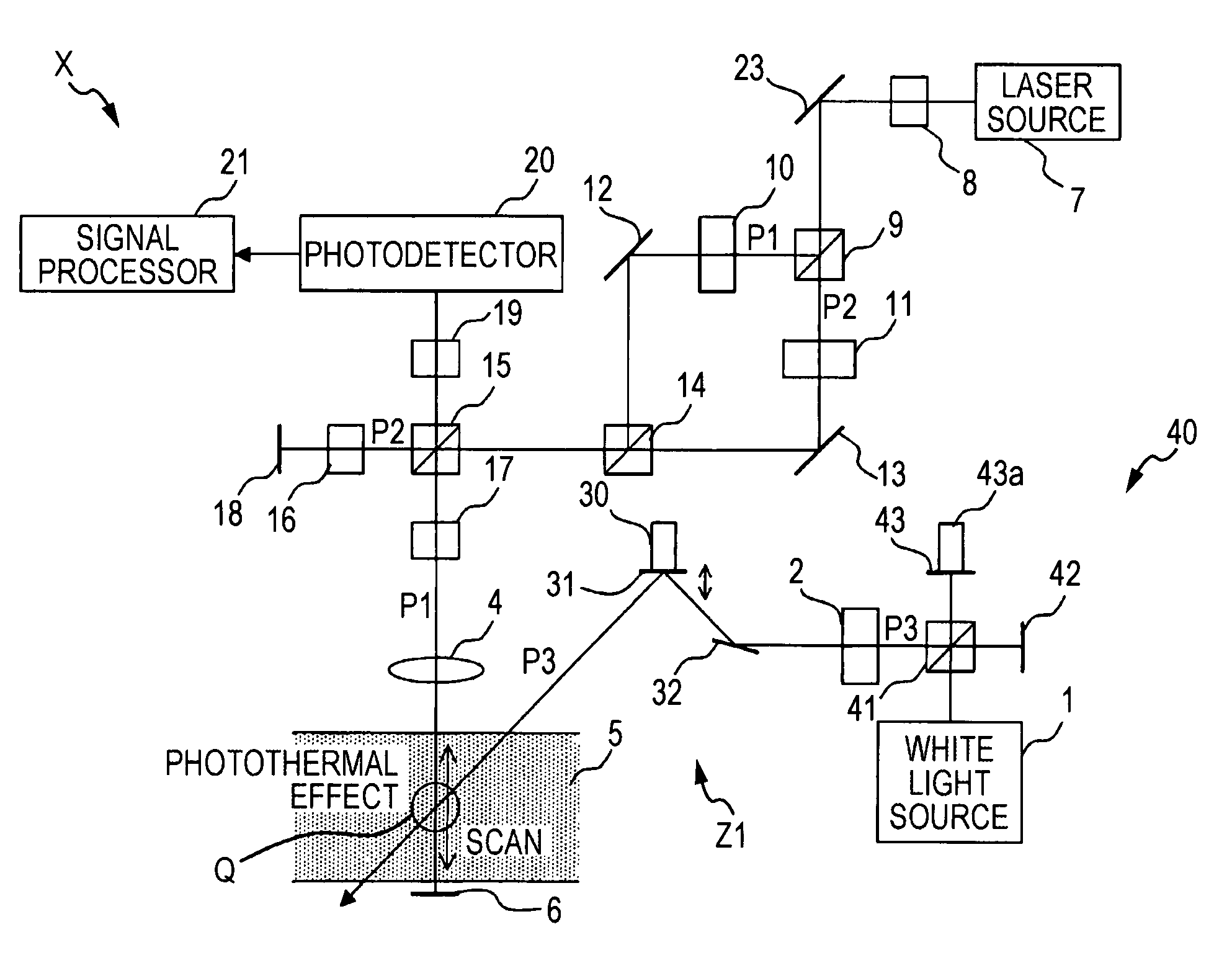
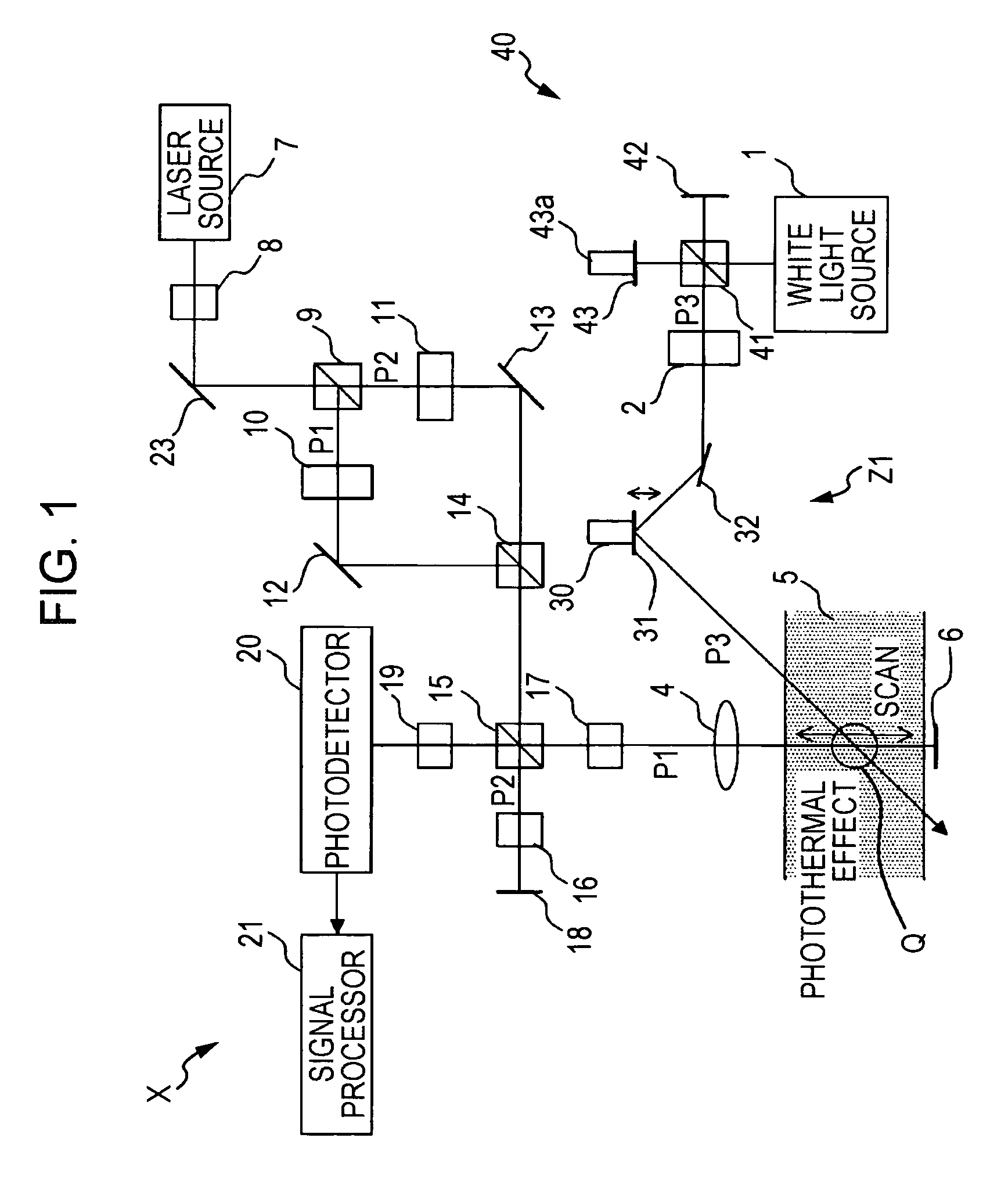
[0109]A photothermal conversion measurement apparatus X according to a first embodiment of the present invention will be described below with reference to FIG. 1.

[0110]Excitation light P3 is emitted from a white light source 1 (e.g., a tungsten lamp), passes through a Fourier spectroscope 40, and is converted (periodically intensity-modulated) into chopped light with a predetermined period (chopping frequency f) by a chopper 2. Then, the optical path of the excitation light P3 is deflected by a measurement-position-changing mechanism Z1 and the excitation light P3 is incident on a liquid sample 5. The sample 5 absorbs the excitation light P3 and generates heat (photothermal effect) that causes a temperature change (increase), and accordingly the refractive index of the sample 5 is changed.

[0111]The Fourier spectroscope 40 is commonly known Fourier spectroscopic means including a beam splitter 41 that divides the light from the white light source 1 into two light components, a fixed ...

second embodiment

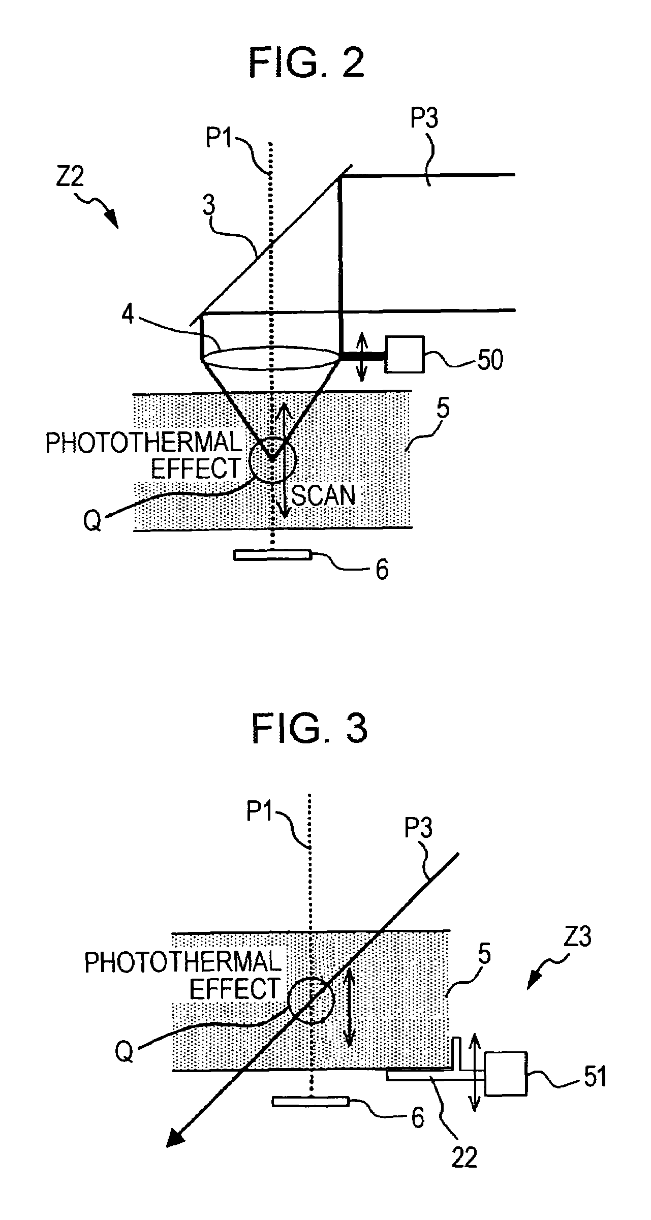
[0136]A measurement-position-changing mechanism Z2 included in a photothermal conversion measurement apparatus according to a second embodiment of the present invention will be described below with reference to FIG. 2.

[0137]Photothermal conversion measurement apparatuses according to second and third embodiments are similar to the above-described photothermal conversion measurement apparatus X except for the structure of the measurement-position-changing mechanism.

[0138]Similar to the measurement-position-changing mechanism Z1, the measurement-position-changing mechanism Z2 shown in FIG. 2 also changes a measurement position Q by moving an optical path of excitation light P3 while a path of measurement light P1 is fixed.

[0139]More specifically, the measurement-position-changing mechanism Z2 (example of second optical-path-changing means) includes a half mirror 3, a lens 4, and a lens-moving unit 50 (example of lens-moving means). The half mirror 3 is placed on the path of the beam-s...

third embodiment

[0144]A measurement-position-changing mechanism Z3 included in a photothermal conversion measurement apparatus according to a third embodiment of the present invention will be described below with reference to FIG. 3.

[0145]The measurement-position-changing mechanism Z3 shown in FIG. 3 changes a measurement position Q by moving the position of a liquid sample 5 while paths of measurement light P1 and excitation light P3 are both fixed. The measurement-position-changing mechanism Z3 includes a support 22 for supporting the sample 5 and a sample-moving unit 51 (example of sample-moving means) including a piezoelectric stage or the like that moves the support 22 along the incident direction of the measurement light P1 on the sample 5.

[0146]In the structure shown in FIG. 3, the support 22 of the sample 5 is moved while the excitation light P3 is incident on the sample 5 in a direction inclined with respect to the incident direction of the measurement light P1. Alternatively, however, the...


PUM

PropertyMeasurementUnit
wavelengthaaaaaaaaaa
frequenciesaaaaaaaaaa
frequencyaaaaaaaaaa

Abstract

A liquid sample is irradiated with excitation light and measurement light, and a measurement position at which a traveling path of the measurement light passes through an excitation section of the excitation light in the sample is changed while the sample is being irradiated with the excitation light and the measurement light. Then, the phase change of the measurement light is measured for each measurement by optical interferometry on the basis of the measurement light after the measurement light passes through the sample. The measurement position is changed by, for example, scanning the excitation light, moving the sample, moving a lens that collects the excitation light in the sample so as to change the light-collecting position (focal position) in the sample, etc.

Description

BACKGROUND OF THE INVENTION[0001]1. Field of the Invention[0002]The present invention relates to a photothermal conversion measurement apparatus and a photothermal conversion measurement method used in a process of analyzing, for example, a substance contained in a liquid sample to measure a property change of the sample based on a change in the refractive index of the sample that is caused by a photothermal effect when the sample is irradiated with excitation light. The present invention also relates to a sample cell that contains the liquid sample to be analyzed.[0003]2. Description of the Related Art[0004]In the analysis of substances contained in samples, such as various kinds of liquid samples, it is important to increase the analytical sensitivity in order to reduce the amounts of reagents, to simplify the process of concentrating the samples, to improve the analytical efficiency, and to reduce costs.[0005]On the other hand, when a portion of a sample is irradiated with excita...

Claims


Application Information

Patent Timeline
Patent Type & Authority Patents(United States)
IPC IPC(8): G01B11/02G01N1/10G01N21/00
CPCG01N21/171G01N21/031G01N2021/1712G01N2021/178G01N2201/105G01N21/45
Inventor TAKAHASHI, EIJITAKAMATSU, HIROYUKIKANNAKA, MASATOSAKODA, NAOKAZUMORIMOTO, TSUTOMU
Owner KOBE STEEL LTD
Learn More