
Optical transmission system using Raman amplification

a technology of optical transmission system and raman, applied in the field of optical transmission network, can solve problems such as commercially viable all-in-one implementation

Active Publication Date: 2009-04-21
CIENA
View PDF7 Cites 34 Cited by
  • Summary
  • Abstract
  • Description
  • Claims
  • Application Information

AI Technical Summary

Benefits of technology

[0015]In such a system, the transmission path dispersion compensator compensates for the total dispersion which accumulates along the transmission path, thus eliminating the need for a dispersion compensator at each span junction. As there is no need for a dispersion compensator at each span junction, there is no longer a need to compensate for the signal loss of the dispersion compensator at each span. Thus, the total gain of an amplifier at each amplifier site only needs to compensate for the transmission loss across the span. This reduces the gain requirements for each span amplifier.
[0019]In a further aspect, the present invention provides a low-cost method for implementing a bidirectional Service Channel by modulating / demodulating low-rate data on the Raman pump. For example, according to an aspect of the invention there is provided a Raman amplifier comprising: a Raman Pump laser for injecting a Raman pump signal into a span of optical fiber; an information source for producing a service channel signal which includes information to be communicated; and a modulator for modulating said Raman pump signal with said service channel signal.

Problems solved by technology

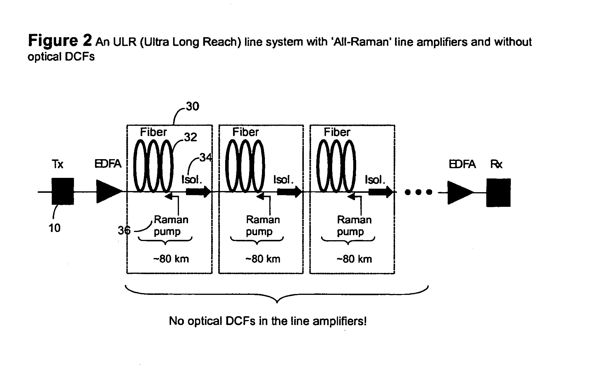
We have realized that including optical dispersion compensators on a per span basis (i.e., in the amplifier sites) is a significant contributor to the difficulty of implementing a commercially viable All-Raman system.

Method used


Image

  • Optical transmission system using Raman amplification
  • Optical transmission system using Raman amplification
  • Optical transmission system using Raman amplification

Examples


Embodiment Construction

[0031]Generally, an aspect of the present invention provides a method and system for implementing a commercially viable All-Raman system, by including a transmission path dispersion compensator which performs dispersion compensation on a transmission path basis.

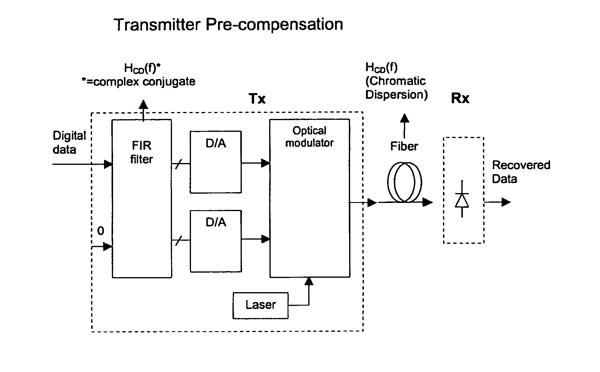
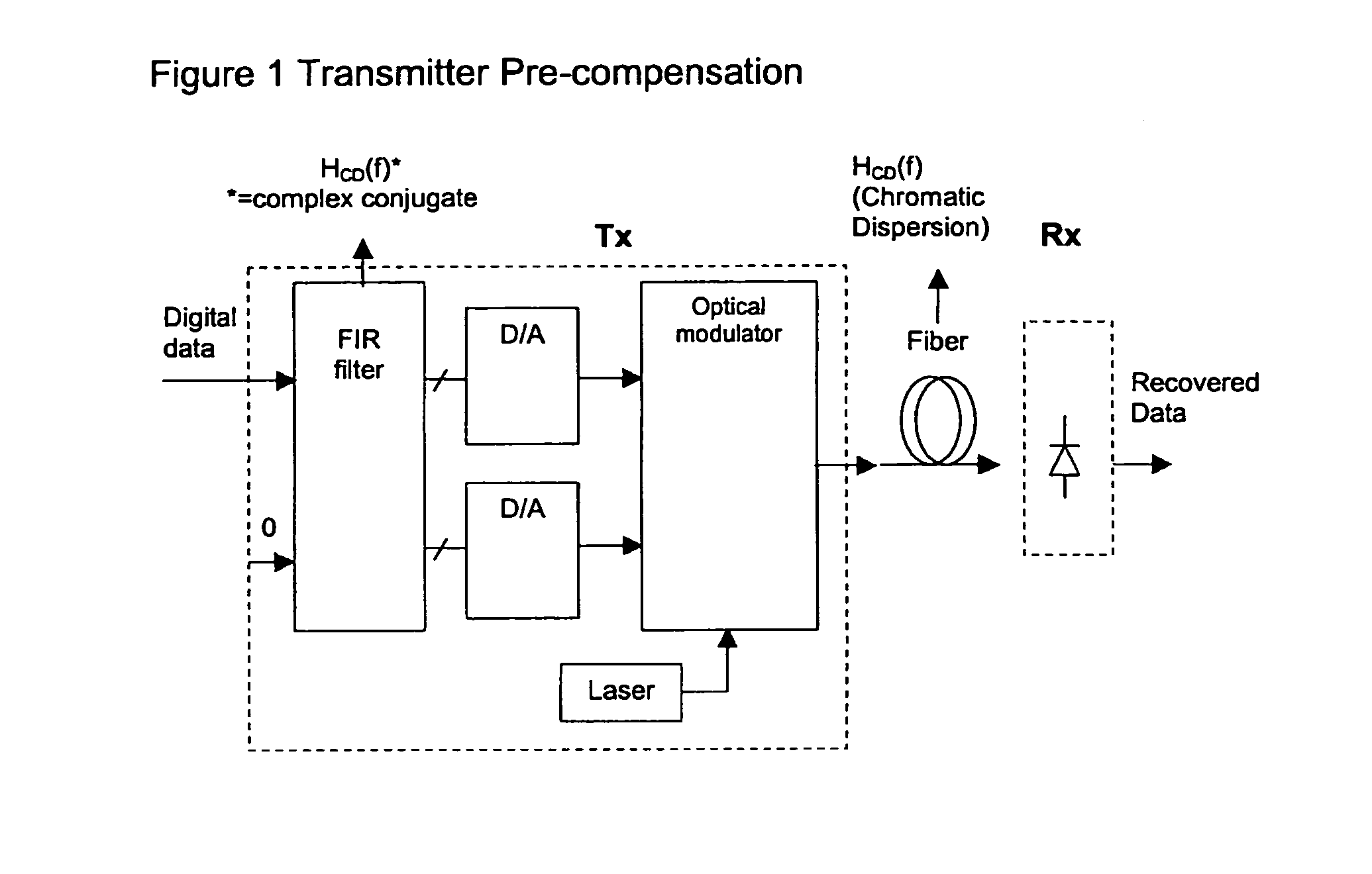
[0032]Nortel Networks Next Generation Modulator (NGM) provides an example of such a system. It compensates for the dispersion on a transmission path basis, by using pre-compensation (in the electrical domain) to add negative compensation at the transmit side. Advantageously, this eliminates the need for a dispersion compensator at each span, and does so without adding additional loss.

[0033]By eliminating the need for DCF, the NGM reduces the gain required by each Raman Pump. This finally enables a commercially viable All-Raman system.

[0034]FIG. 1 shows the functional block diagram of a transmitter which includes a transmission path dispersion compensator, according to an embodiment of the invention. In this example, the trans...


PUM


Abstract

A commercially viable All-Raman system, is implemented by removing the dispersion compensating Fiber (DCF) and two stage amplifier at each span, and including a transmission path dispersion compensator which performs dispersion compensation on a transmission path basis. For example, by pre-compensating for the accumulated dispersion in the electrical domain at the transmitter, the gain of the Raman pumps at each span amplifier need only compensate for the loss within the span, without needing to compensate for the loss of a DCF. In addition there is provided a low-cost method for implementing a bidirectional Service Channel by modulating / demodulating low-rate data on the Raman pump. For example, a Raman amplifier can include an information source for producing a service channel signal which includes information to be communicated; and a modulator for modulating the Raman pump signal with the service channel signal.

Description

CROSS REFERENCE TO RELATED APPLICATIONS[0001]This application claims the benefit of U.S. application Ser. No. 10 / 262,944 filed Oct. 3, 2002, and assigned to the assignee of the present application, which is incorporated herein by reference.FIELD OF THE INVENTION[0002]The present invention relates generally to optical transmission networks. More particularly, the present invention relates to optical transmission networks which require amplification and dispersion compensation. An aspect of the invention relates to transmitting information between nodes.BACKGROUND OF THE INVENTION[0003]A known problem with conventional optical transmission systems is the loss of power as an optical signal propagates through the transmission path between optical nodes. A well known solution to this problem involves dividing the transmission path into spans. Each span ends with an optical amplifier site (hereafter “amplifier”), which amplifies the signal in the optical domain, to compensate for the loss...

Claims


Application Information

Patent Timeline
IPC IPC(8): H04B10/08H04B10/00H04J14/02
CPCH04B10/2916
Inventor MCNICOL, JOHNWU, KUANG TSAN
Owner CIENA
Learn More