
Power output apparatus, method of controlling power output apparatus, and automobile with power output apparatus mounted thereon

a technology of power output apparatus and power output device, which is applied in the direction of engine-driven generators, electric devices, machines/engines, etc., can solve the problems of failure to output the required braking force to the drive shaft, deterioration of drivability, etc., and achieve the effect of preventing drivability deterioration and preventing drivability

Inactive Publication Date: 2009-04-28
TOYOTA JIDOSHA KK
View PDF19 Cites 13 Cited by
  • Summary
  • Abstract
  • Description
  • Claims
  • Application Information

AI Technical Summary

Benefits of technology

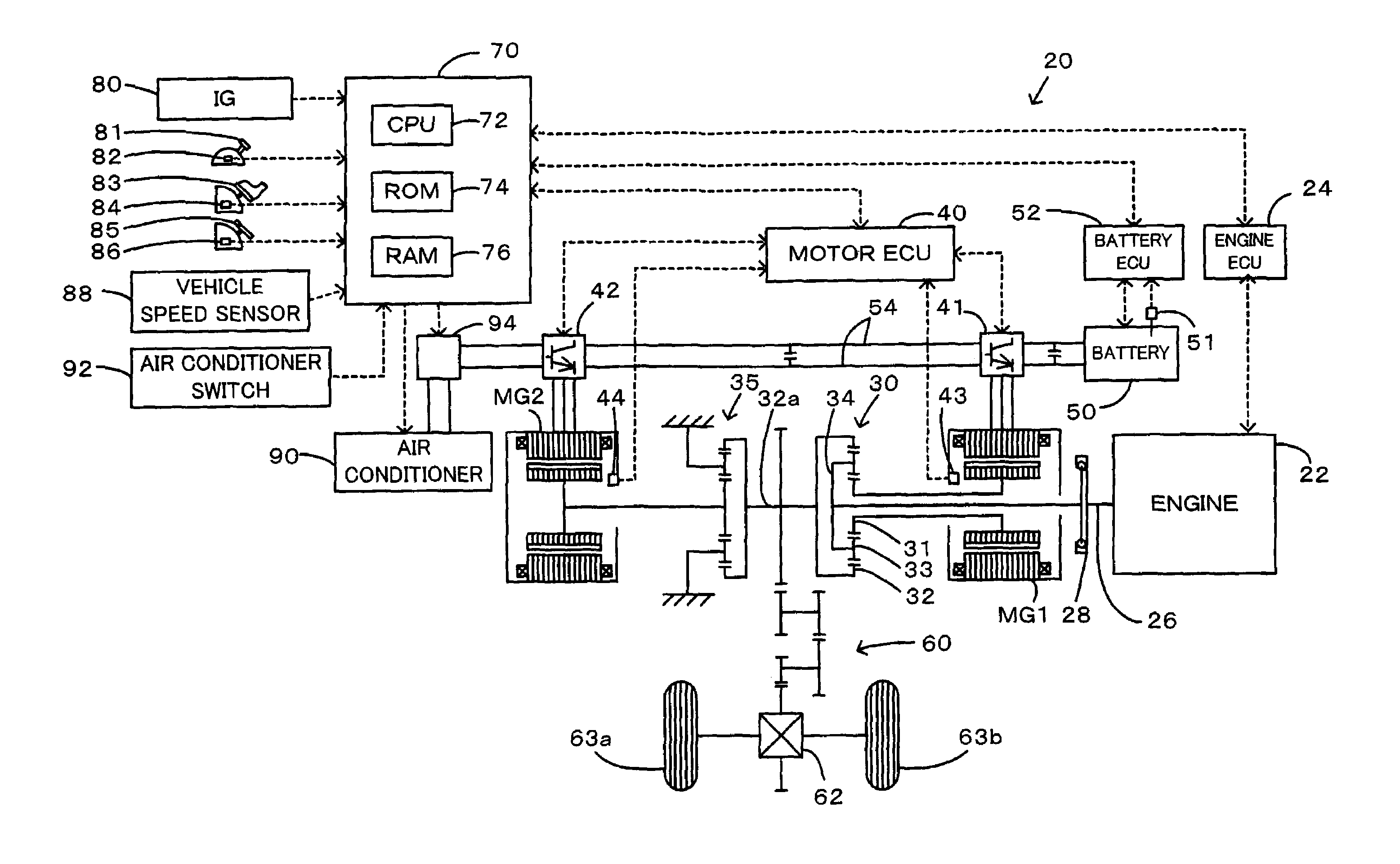
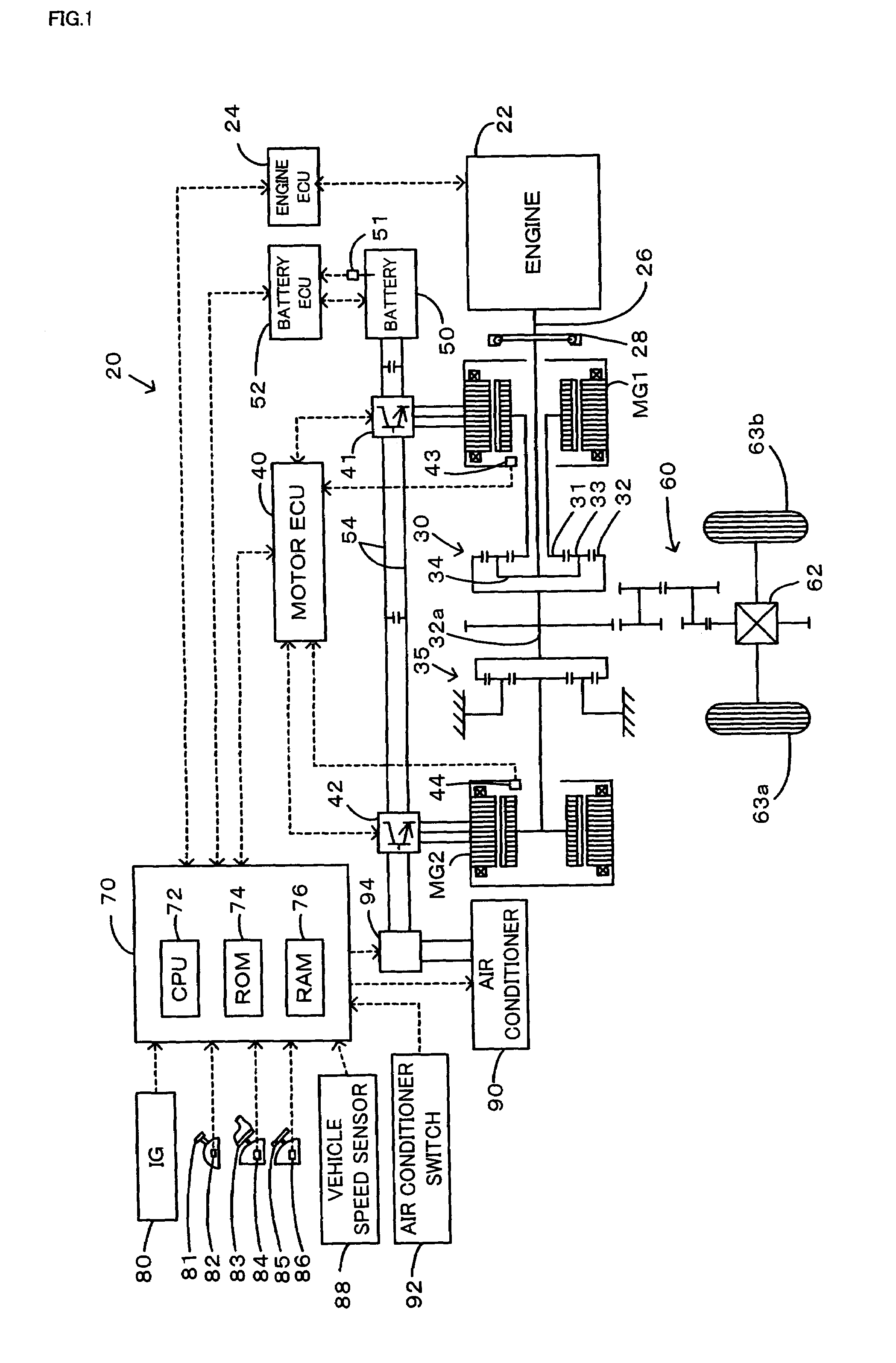
[0006]A power output apparatus of the invention and a corresponding method of controlling the power output apparatus aim to ensure output of a required braking force in response to a driver's accelerator-off action and thereby prevent deterioration of drivability, while preventing an electric accumulator, such as a battery, from being excessively charged. An automobile of the invention also aims to ensure output of a required braking force in response to a driver's accelerator-off action and thereby prevent deterioration of drivability, while preventing an electric accumulator, such as a battery, from being excessively charged.
[0016]The third power output apparatus of the invention sets the target power to be output from the internal combustion engine by the first technique, which sets the target power based on a requirement of a driving force to the drive shaft in response to a driver's operation. In response to the driver's accelerator-off action, the third power output apparatus adopts the second technique, in place of the first technique, to set a power, which is lower than the setting of the target power based on the requirement of the driving force by the first technique, to the target power to be output from the internal combustion engine. The third power output apparatus controls the internal combustion engine to be driven with the setting of the target power, while controlling the electric power-dynamic power input-output module and the motor to output a driving force corresponding to the requirement of the driving force to the drive shaft. Due to the decrease in power output from the internal combustion engine, this arrangement reduces the level of the electric power output from the electric power-dynamic power input-output module and the motor to charge the electric accumulator. The third power output apparatus of the invention thus ensures output of the required driving force to the drive shaft in response to the driver's accelerator-off action, while satisfying the charge limit of the electric accumulator.
[0020]As one application of the fourth power output apparatus of the invention, the controller may forcibly activate the auxiliary machinery to consume the surplus electric power exceeding the charge limit of the electric accumulator. As another application of the fourth power output apparatus of the invention, when it is expected that a surplus electric power exceeding the charge limit of the electric accumulator is generated by the control of the internal combustion engine, the electric power-dynamic power input-output module, and the motor to output the required driving force to the drive shaft, the controller may control the internal combustion engine, the electric power-dynamic power input-output module, and the motor to make the electric power-dynamic power input-output module motor the internal combustion engine and thereby consume the surplus electric power, while outputting the required driving force to the drive shaft, and the controller may forcibly activate the auxiliary machinery, when the motoring of the internal combustion engine by the electric power-dynamic power input-output module fails to use up all the surplus electric power exceeding the charge limit of the electric accumulator. When it is expected that the control generates a surplus electric power exceeding the charge limit of the electric accumulator, the structure of this application causes the electric power-dynamic power input-output module to motor the internal combustion engine and thereby consume the surplus electric power. In the case where the motoring of the internal combustion engine by the electric power-dynamic power input-output module does not manage to use up all the surplus electric power, the structure of this application forcibly activates the auxiliary machinery to consume the residue of the surplus electric power exceeding the charge limit of the electric accumulator and thereby effectively prevents the electric accumulator from being excessively charged.
[0024]The fifth power output apparatus of the invention sets a specific drive point of the internal combustion engine to output a required driving force to the drive shaft, actuates and controls the internal combustion engine, the first AC motor, and the second AC motor to drive the internal combustion engine at the preset specific drive point and to ensure output of a driving force corresponding to the required driving force to the drive shaft, and carries out surplus electric power consumption control in the presence of a surplus electric power exceeding a charge limit of the electric accumulator. The surplus electric power consumption control actuates and controls the first AC motor and the second AC motor to make at least part of the surplus electric power consumed by at least one of the first AC motor and the second AC motor through input and output of an invalid component of electric power having no contribution to generation of driving force. This arrangement effectively prevents the electric accumulator from being excessively charged or being charged with excess voltage, while ensuring output of the driving force corresponding to the required driving force to the drive shaft. At least part of the surplus electric power is consumed by the first AC motor or by the second AC motor. There is accordingly no need of providing any additional device for consumption of the surplus electric power.

Problems solved by technology

This may fail to output the required braking force to the drive shaft and deteriorate the drivability.

Method used


Image

  • Power output apparatus, method of controlling power output apparatus, and automobile with power output apparatus mounted thereon
  • Power output apparatus, method of controlling power output apparatus, and automobile with power output apparatus mounted thereon
  • Power output apparatus, method of controlling power output apparatus, and automobile with power output apparatus mounted thereon

Examples


second embodiment

[0074]The hybrid vehicle of the second embodiment sets the difference between the tentative target power Petmp1 and the smoothed target power Petmp2 gained by smoothing the tentative target power Petmp1 to the undershoot Peus. Such setting is, however, not restrictive at all, but any preset value may be set to the undershoot Peus.

[0075]The following describes a hybrid vehicle of a third embodiment. The hybrid vehicle of the third embodiment has the identical construction with that of the hybrid vehicle 20 of the embodiment, except some differences of processing executed by the hybrid electronic control unit 70. The constituents of the hybrid vehicle of the third embodiment that are identical with those of the hybrid vehicle 20 of the embodiment are expressed by the same numerals and symbols and are not specifically described here. FIG. 6 is a flowchart showing a third drive control routine, which is executed by the hybrid electronic control unit 70 in the hybrid vehicle of the third...

third embodiment

[0082]After the power consumption Pair of the air conditioner 90 is set at step S322, when it is determined at step S312 that the torque command Tm2* of the motor MG2 is not less than the motor torque limit Tm2lim, or when it is determined at step S318 that the target revolution speed Ne* of the engine 22 is not higher than the engine revolution speed limit Nelim, the CPU 72 sends the settings of the target revolution speed Ne* and the target torque Te* of the engine 22 to the engine ECU 24, while sending the settings of the torque command Tm1* and the target revolution speed Nm1* of the motor MG1 and the torque command Tm2* of the motor MG2 to the motor ECU 40 (step S324). In the case of setting the power consumption Pair of the air conditioner at step S322, the CPU 72 forcibly activates the air conditioner 90 with the power consumption Pair, regardless of the on-off state of the air conditioner switch 92 (step S324). The program then exits from this third drive control routine. In...

fourth embodiment

[0095]When it is determined at step S458 that there is the surplus electric power Psur, on the other hand, the motor ECU 40 specifies the possibility of the battery 50 being excessively charged or being charged with excessive voltage. The motor ECU 40 accordingly modifies the current command Id2* of the motor MG2 set at step S456 according to Equation (24) given below to apply an invalid electric power having no torque contribution and thereby make the motor MG2 consume the surplus electric power Psur (step S460), prior to the actuation and control of the motors MG1 and MG2 at steps S462 through S468. In Equation (24), K denotes a conversion coefficient to the voltage of the motor MG2. This motor control process applies an invalid electric power having no contribution to generation of a torque and thereby makes the motor MG2 consume the surplus electric power, which is not acceptable by the battery 50. This arrangement effectively prevents the battery 50 from being charged excessive...


PUM


Abstract

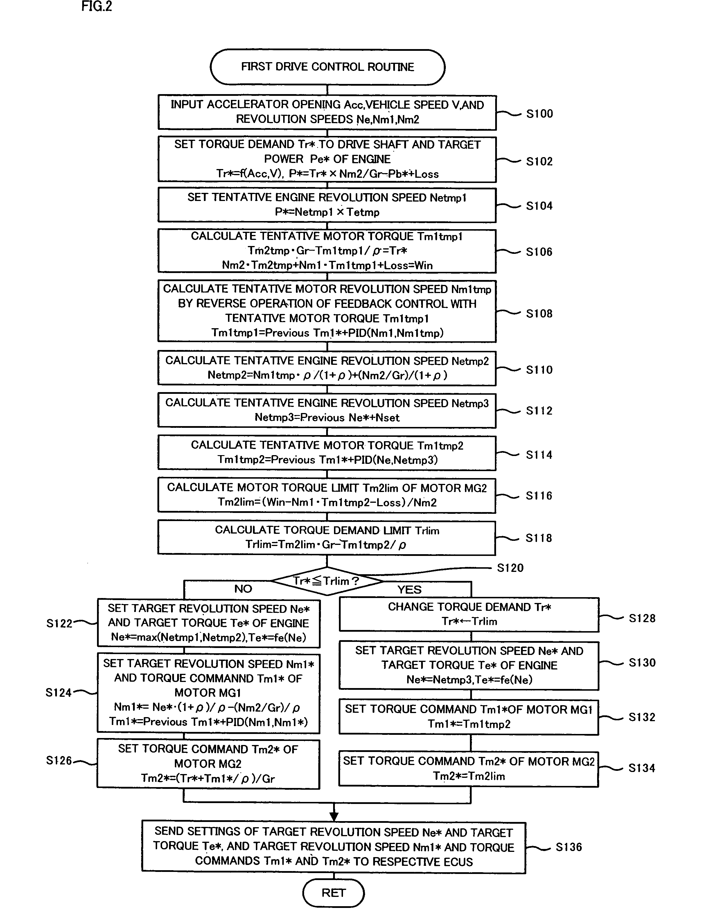
The procedure of the invention sets a revolution speed at an efficient drive point, which is selected among drive points of an engine fulfilling a target power Pe* to be output from the engine, to a tentative revolution speed Netmp1 of the engine. The procedure also calculates a revolution speed that satisfies both a torque demand Tr* to be output to a drive shaft and a charge limit Win of a battery or an electric accumulator and sets the calculated revolution speed to a tentative revolution speed Netmp2 of the engine. The procedure sets the grater between the tentative revolution speed Netmp1 and the tentative revolution speed Netmp2 to a target revolution speed Ne* of the engine and controls the engine and two motors. This arrangement ensures output of a required braking force in response to a driver's accelerator-off action, while taking into account the charge limit of the electric accumulator.

Description

BACKGROUND OF THE INVENTION[0001]1. Field of the Invention[0002]The present invention relates to a power output apparatus, a method of controlling the same, and an automobile with the power output apparatus mounted thereon. More specifically the invention pertains to a power output apparatus that outputs power to a drive shaft, as well as to a method of controlling such a power output apparatus and an automobile with such a power output apparatus mounted thereon.[0003]2. Description of the Prior Art[0004]A proposed power output apparatus has an engine, a planetary gear mechanism that includes a carrier connected with a crankshaft of the engine and a ring gear connected with a drive shaft, which is mechanically linked with an axle, a first motor that outputs power to a sun gear of the planetary gear mechanism, a second motor that inputs and outputs power from and to the drive shaft, and a battery that transmits electric power to and from the first motor and the second motor (for exam...

Claims


Application Information

Patent Timeline
Patent Type & Authority Patents(United States)
IPC IPC(8): B60K6/48B60W20/00B60K1/02B60K6/28B60K6/365B60K6/445B60K6/52B60L7/16B60L50/16B60W10/06B60W10/08B60W10/30F02D29/02F02D29/06F16H3/72
CPCB60K6/365B60K6/445B60L1/003B60L3/0046B60L7/14B60L7/20B60L7/26B60L11/123B60L11/14B60W10/06B60W10/08B60W10/30B60W20/00B60K1/02B60L2210/40B60L2220/14B60L2240/12B60L2240/421B60L2240/423B60L2240/441B60L2240/443B60L2240/545B60W2510/244B60W2520/26B60W2540/10B60W2710/0644F16H3/727F16H2037/0866Y02T10/56Y02T10/6217Y02T10/6286Y02T10/7077Y02T10/7005Y02T10/7241Y02T10/642Y02T10/6239B60L50/61B60L50/16B60L58/15Y02T10/40Y02T10/62Y02T10/64Y02T10/72Y02T10/7072Y02T10/70B60W30/18109B60W20/13
Inventor KIMURA, AKIHIRONOZAWA, NATSUKI
Owner TOYOTA JIDOSHA KK
Learn More