Fuel injection valve

a fuel injection valve and valve body technology, applied in liquid fuel feeders, machines/engines, engine components, etc., can solve the problems of unstable operation, difficult task of known control strategies, and difficulty in controlling the quantity of fuel, so as to reduce variability in the fuel mass flow rate and maintain the constant mass flow rate

Active Publication Date: 2009-05-05
WESTPORT POWER
View PDF22 Cites 48 Cited by
  • Summary
  • Abstract
  • Description
  • Claims
  • Application Information

AI Technical Summary

Benefits of technology

[0018]To reduce the variability in flow rate when the valve needle is positioned between the first and second intermediate positions, the constant flow area is preferably smaller than the open flow area between the valve seat so that the constant flow area controls the fuel mass flow rate through the fuel injection valve when the valve needle is positioned between the first and second intermediate positions.
[0023]The valve needle can be an inward opening valve needle whereby the valve needle is movable in an inward direction opposite to the direction of fuel flow when moving from the closed position towards the open position. In this embodiment the nozzle can comprise a closed end with at least one orifice through which the fuel can be injected when the valve needle is spaced apart from the valve seat. In preferred embodiments, the nozzle comprises a plurality of orifices through which the fuel can be injected when the valve needle is spaced apart from the valve seat and the collective open area of the plurality of orifices is greater than the constant flow area. When the valve needle is in the fully open position, the collective open area of the plurality of orifices provides the smallest restriction for the fuel flowing through the nozzle and thereby governs the mass flow rate of fuel flowing through the fuel injection valve.
[0027]Preferably the method further comprises commanding the valve needle to the mid-point, between the first and second intermediate positions when the substantially constant mass flow rate is desired. Because there can be some variability between the commanded needle position and the actual needle position, commanding the valve needle to the mid-point of the range of movement reduces the likelihood of the actual valve needle position being outside of the range of movement defined by the predetermined first and second intermediate positions. Overall, this reduces variability in the fuel mass flow rate delivered into the combustion chamber.
[0029]In a preferred embodiment of the method, providing a flow restriction within the nozzle with a constant flow area when the valve needle is positioned between the first and second intermediate positions regulates the substantially constant fuel mass flow rate. When the second intermediate position corresponds to a larger valve needle lift than that of the first intermediate position, fuel mass flow rate can be substantially and progressively increased by moving the valve needle from the second intermediate position toward the fully open position.
[0030]The method can further comprise commanding the valve needle to a position between the second intermediate position and a third intermediate position when a second substantially constant mass flow rate is desired, where the second intermediate position corresponds to a larger valve needle lift than that of the first intermediate position and the third intermediate position corresponds to a larger needle lift than that of the second intermediate position. The fuel injection valve can be designed with flow restrictions such that the first restricted flow area is smaller than the second restricted flow area that is substantially constant when the valve needle is positioned between the second and third intermediate positions. In this embodiment of the method, the fuel mass flow rate can be substantially and progressively increased by moving the valve needle from the third intermediate position toward the fully open position. For example, the first constant mass flow rate can be selected when the engine is idling and the second constant mass flow rate can be selected when the engine is operating under predetermined low load conditions.
[0035]Similarly, the method can further comprise controlling injection pressure to assist with controlling the amount of fuel that is injected during an injection event, whereby fuel injection pressure is variable from one injection event to another responsive to predetermined measured engine operating conditions.

Problems solved by technology

Shibata does not disclose an apparatus or method for regulating fuel mass flow by actuating a valve needle that is operable to hold the valve needle at intermediate positions and a method whereby the valve needle lift is variable both during an injection event and from one injection event to another injection event.
That is, Shibata does not disclose an apparatus or method that allows partial valve needle lift to an intermediate position for the duration of an injection event so that the lower mass flow rate is provided for the entire injection event, and that also allows valve lift to a fully open position for another injection event.
A difficult task for known control strategies is controlling the quantity of fuel that is injected into an engine's combustion chamber under idle or low load conditions.
Under such conditions the fuel injection valve is required to inject only a small amount of fuel into the combustion chamber, and even small variations in the quantity of fuel that is injected into the combustion chamber can result in a significant variance in the injected quantity of fuel that can cause unstable operation.
To control the quantity of fuel injected during idle and low load conditions, if the control strategy manipulates only pulse width, this strategy can result in a pulse width that is too short to provide consistent and efficient combustion.
Accordingly, simply shortening pulse width at idle or low load conditions to reduce the quantity of injected fuel is not a desirable strategy.
For liquid fuels this is a viable strategy, but it requires a system for controlling fuel pressure, adding to the cost and complexity of the fuel injection system.
With liquid fuels, there are limitations on how low the pressure can be reduced since a minimum fuel pressure is required to atomize the fuel when it is introduced into the engine's combustion chamber.
However, this approach is more difficult with a gaseous fuel.
Consequently, it can be difficult to rapidly reduce the pressure of a gaseous fuel without venting some of the fuel to atmosphere, which is undesirable.
Accordingly, it can be difficult to control fuel pressure to achieve the desired responsiveness for controlling the fuel injection mass flow rate during an injection event or from one injection event to the next.
It can also be difficult to control fuel pressure and injection valve operation to accurately inject the exact quantity of fuel with the precision desired for each injection event, and again, only small variations in fuel quantity can cause unstable operating conditions.
Therefore, controlling fuel injection pressure alone is not a desirable strategy for regulating fuel mass flow rate through a fuel injection valve.
This type of mechanical arrangement adds considerable complexity to the fuel injection valve and, consequently, higher manufacturing costs, space requirements for installing the injection valve assembly, maintenance costs, and reliability concerns.
Like other known mechanical solutions this arrangement adds complexity and the associated disadvantages of higher manufacturing costs, maintenance costs, and concerns for reliability.
However, even with this approach there can be variability of fuel flow from one injection event to the next because the actual valve needle lift may not always accurately match the commanded lift.
Accordingly, even with a fuel injection valve that employs an actuator that allows lift control, there can be factors that cause variability in the actual lift that can still be large enough to cause variability in the quantity of injected fuel.
Engine instability at idle and low load conditions can cause higher engine fuel consumption, exhaust emissions, noise and vibration.
It can be difficult to operate a conventional fuel injection valve to provide the stepped flow characteristic that is needed to achieve this result.

Method used


Image

  • Fuel injection valve
  • Fuel injection valve
  • Fuel injection valve

Examples


Embodiment Construction

)

[0049]The schematic views are not drawn to scale and certain features may be exaggerated to better illustrate their functionality.

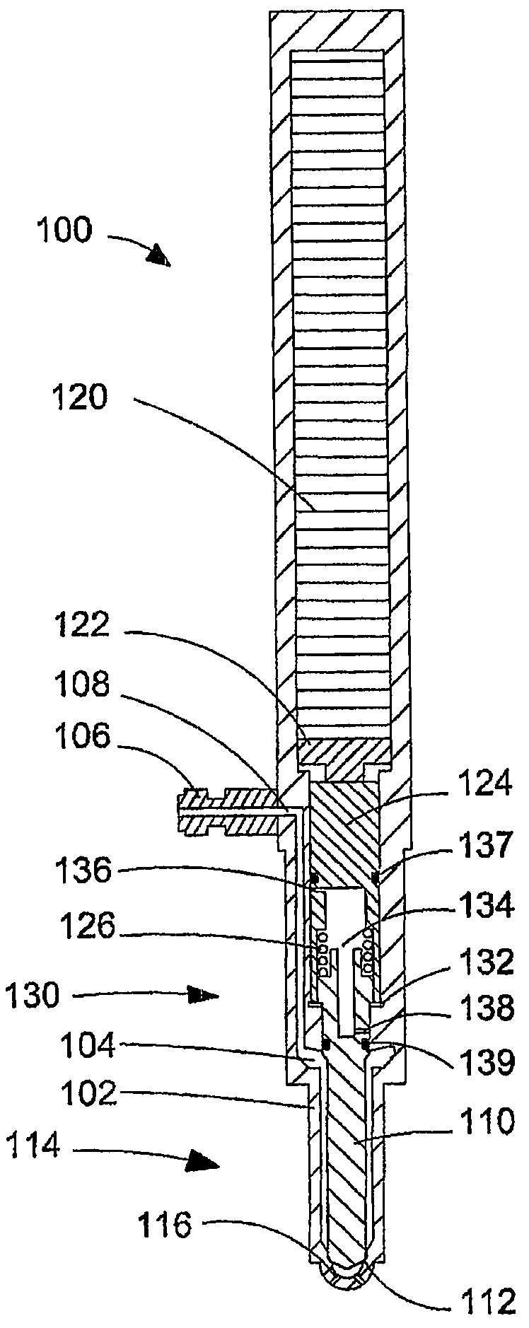
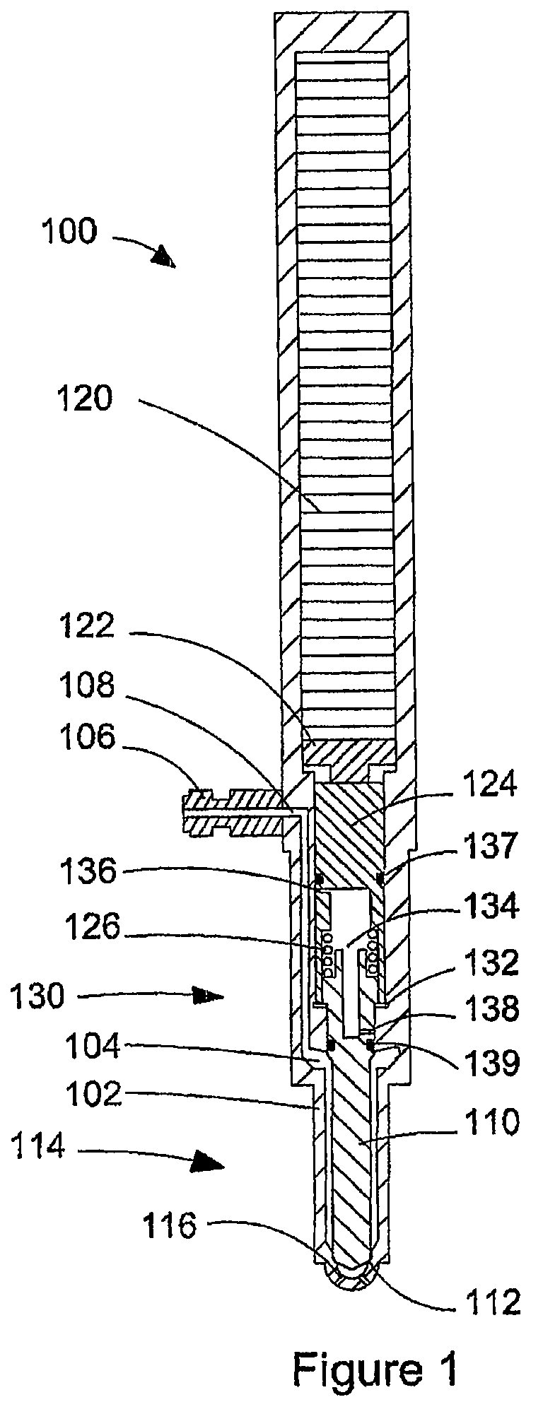
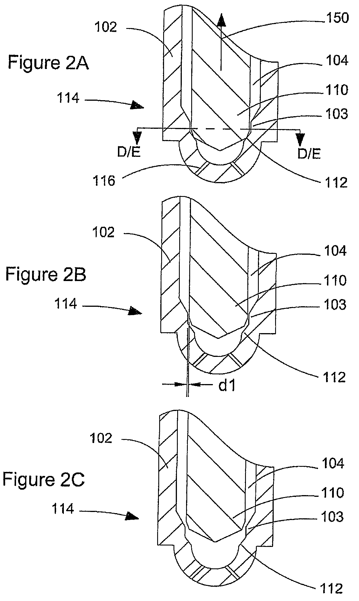
[0050]FIG. 1 is a schematic cross-sectional view of fuel injection valve 100, which can be employed to introduce fuel into an engine. Valve body 102 houses valve needle 110, actuator 120, and transmission assembly 130. Valve body 102 also defines fuel cavity 104, which comprises fuel passages extending from coupling 106 and fuel inlet 108 through to valve seat 112. Valve needle 110 is movable within nozzle 114 between a closed position at which valve needle 110 is seated against valve seat 112 and a fully open position at which valve needle 110 is spaced furthest apart from valve seat 112. When valve needle 110 is spaced apart from valve seat 112, fuel can flow from fuel cavity 104 into the engine through nozzle 114. In the example illustrated by FIG. 1, fuel exits nozzle 114 through orifices 116. In the case of an outward opening valve needle (see for e...


PUM


Abstract

A fuel injection valve introduces a fuel into an engine and controlling fuel flow to reduce variability between injection events. The fuel injection valve employs an arrangement for a valve nozzle that cooperates with a valve needle to provide a range of needle movement within which the fuel mass flow rate is substantially constant. This can be achieved by providing a restriction with a constant flow area for a predetermined range of needle movement. The method comprises commanding a valve needle to a position within the predetermined range of needle movement to reduce variability in the fuel mass flow rate, particularly when the engine is idling or operating under low load conditions. Valve needle lift is variable during an injection event and from one injection event to another injection event.

Description

CROSS-REFERENCE TO RELATED APPLICATION(S)[0001]This application is a continuation of International Application No. PCT / CA2005 / 001062, having an international filing date of Jan. 8, 2005, entitled “Fuel Injection Valve”. International Application No. PCT / CA2005 / 001062 claimed priority benefits, in turn, from Canadian Patent Application No. 2,473,639 filed Jul. 9, 2004. International Application No. PCT / CA2005 / 001062 is hereby incorporated by reference herein in its entirety.FIELD OF THE INVENTION [0002]The present invention relates to a fuel injection valve and a method of operating such a fuel injection valve for controlling fuel flow into an internal combustion engine. More particularly, the fuel injection valve comprises a nozzle arrangement that provides a substantially constant flow rate for a predetermined range of valve needle movement.BACKGROUND OF THE INVENTION [0003]A fuel injection valve can employ a number of control strategies for governing the quantity of fuel that is i...

Claims


Application Information

Patent Timeline
Patent Type & Authority Patents(United States)
IPC IPC(8): F02M37/04F02M51/00
CPCF02M51/0603F02M61/18F02M61/1806F02M61/08F02M2200/703
Inventor WING, RICHARDLOCKLEY, IANOVERSBY, KEVIN
Owner WESTPORT POWER
Why Eureka
Try Eureka