Seat back structure of vehicle seat

a vehicle seat and seat back technology, applied in the direction of chairs, pedestrian/occupant safety arrangements, vehicular safety arrangements, etc., can solve the problems of excessive backward inclination of the seat back frame or seat back, counterforce or resistance, and seat back load, etc., to achieve the effect of improving the seat back structure and simplifying the structur

Inactive Publication Date: 2009-05-12
TACHI S CO LTD
View PDF10 Cites 102 Cited by
  • Summary
  • Abstract
  • Description
  • Claims
  • Application Information

AI Technical Summary

Benefits of technology

[0006]In view of the afore-stated drawbacks, it is a primary purpose of the present invention to provide an improved seat back structure in a vehicle seat, which is simplified in

Problems solved by technology

However, such biasing arrangement gives a full biasing force of the biasing means directly to both of the auxiliary frame and headrest, which undesirably results in giving a counterforce or resistance to the afore-discussed quick forward displacement of those auxiliary frame and headrest in the case of rear-end collision.
Consequently, this prior art has been with the following problems: (i) When a minor rear-end collision occurs under a relatively slow speed of rearward vehicle, the auxiliary frame is slowly displaced in the forward direction due to a weak inertia or a week backward load being applied from the seat occupant and therefore, such week backward load is almost counterbalanced by the biasing force of the biasing means, so that the forward displacement of auxiliary frame becomes slow and therefore the occupant's head is not quickly received and supported by the headrest, and (ii), on the other hand, when a great abrupt r

Method used


Image

  • Seat back structure of vehicle seat
  • Seat back structure of vehicle seat
  • Seat back structure of vehicle seat

Examples


Embodiment Construction

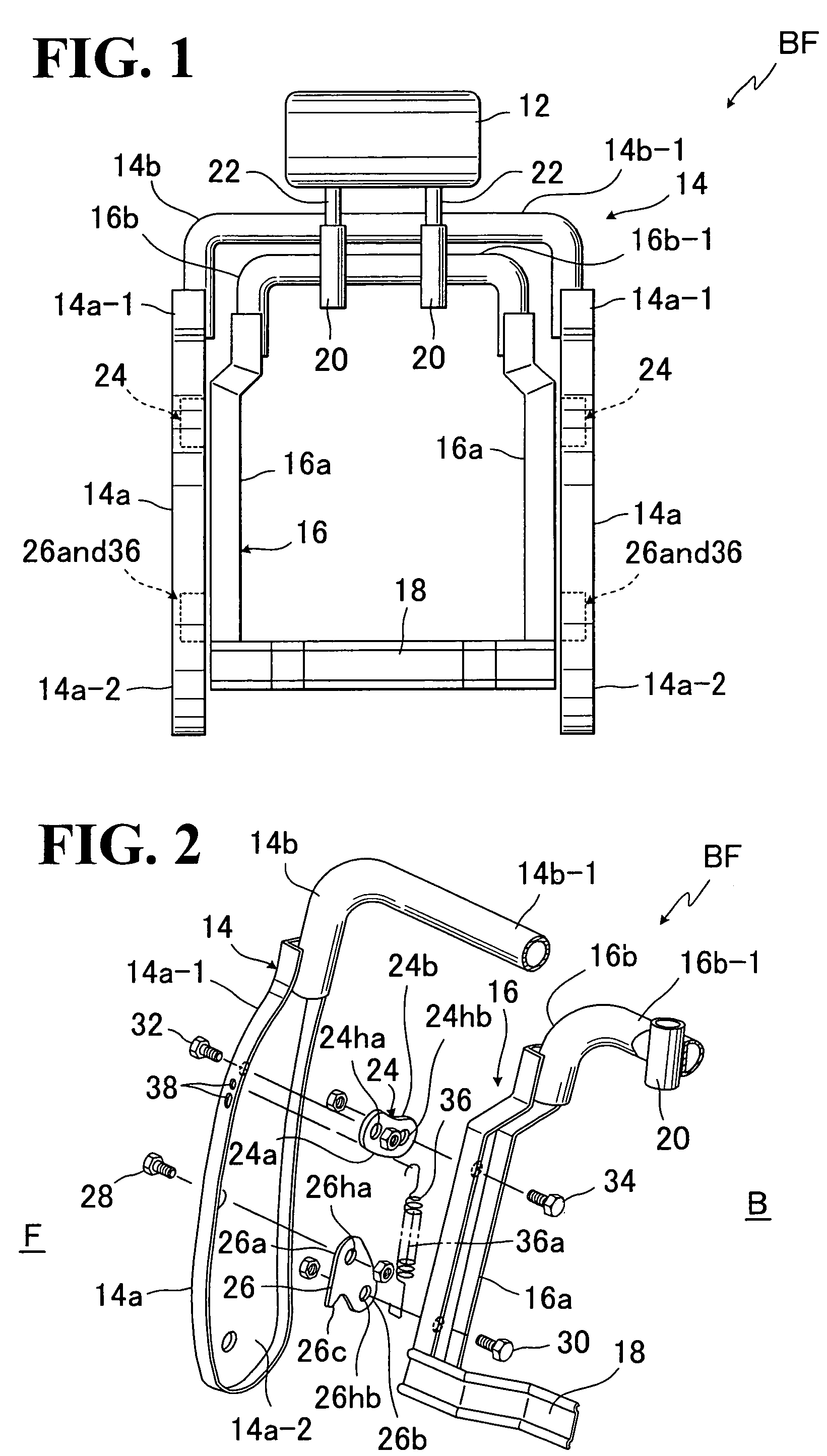
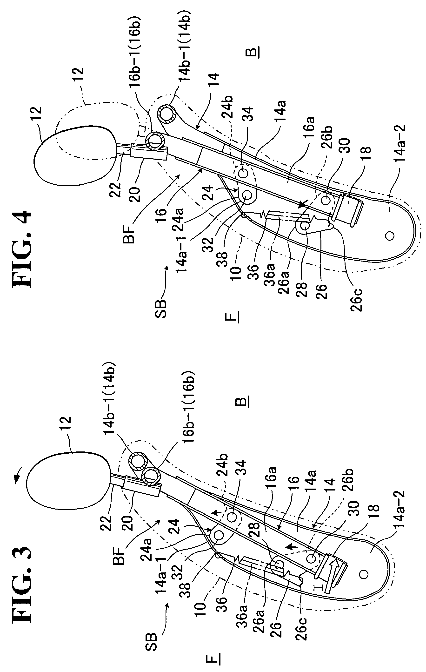
[0029]Referring first to FIG. 1, a generic and basic structure of seat back for vehicle seat in accordance with the present invention is illustrated, which commonly and generically covers one embodiment of seat back structure shown in FIGS. 2 to 4 and another alternative embodiment of seat back structure shown in FIGS. 5 to 8, within the gist and scopes of the present invention. Hence, it should be noted that those two embodiments are simply provided by way of preferred examples and not limitative.

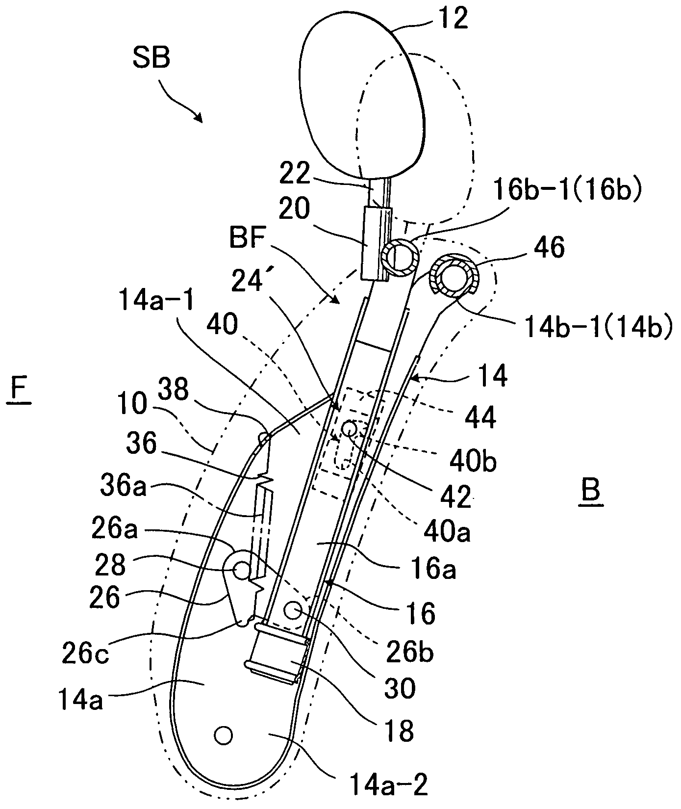
[0030]FIG. 1 shows a backrest framework (BF) which is upholstered as indicated by (10) to form a seat back (SB) as seen from FIG. 3. The backrest framework (BF) is basically composed of a seat back frame (14) and an auxiliary frame (16) disposed inwardly of the seat back frame (14). The seat back frame (14) is a generally “inverted U” shape comprising an upper frame member (14b) and a pair of side frame members (14a) (14a). The auxiliary frame (16) is also of a generally “inverted U” shape...


PUM


Abstract

In a seat back structure, an auxiliary frame having a pressure receiving portion and a headrest mounted thereon is movably provided in seat back frame via guide element and link element. The guide and link elements are respectively disposed in upper and lower portions respectively of the auxiliary and seat back frames. Biasing element is provided to the link element, such that a line of force of the former is positioned on one side of a pivotal point of the link element, thereby retaining the headrest at initial position, and that, when excessive backward load is applied to the pressure receiving portion, the link element is rotated to displace the line of force toward another side of the first pivotal point, whereby the auxiliary frame is displaced forwardly and upwardly of the seat back frame, thereby causing the headrest to move to a position for supporting a head of seat occupant.

Description

BACKGROUND OF THE INVENTION[0001]1. Field of the Invention[0002]The present invention relates to a seat back of vehicle seat with a movable headrest. In particular, the invention is directed to a structure of seat back of seat for vehicle which permits a headrest mounted in the seat back to be displaceable in forward and upward directions in response to a rear-end collision occurred to the vehicle.[0003]2. Description of Prior Art[0004]Among vehicle seats with headrest, there has been known a vehicle seat of such type that, responsive to a rear end collision, a headrest mounted thereon is subjected to forward movement under a backward force of inertia applied from a waist portion of the occupant and moved toward a head portion of occupant on the seat. For example, the Japanese Laid-Open Patent Publication No. 2001-26232 discloses the vehicle seat of this kind. According thereto, the seat back thereof includes a seat back frame and an auxiliary frame, such that a lower portion of the...

Claims


Application Information

Patent Timeline
IPC IPC(8): B60N2/42
CPCB60N2/4885B60N2/888
Inventor YOKOTA, MASAAKIKOIKE, ATSUSHI
Owner TACHI S CO LTD
Why Eureka
Try Eureka