Self-start synchronous motor with permanent magnets and at least one frictional agitation joint, method for manufacturing the same and compressor comprising the same

a synchronous motor and permanent magnet technology, applied in the direction of synchronous motors, rotors, cage rotors, etc., can solve the problems of permanent magnet deterioration and difficulty in further enhancing efficiency, and achieve the effect of preventing permanent magnet deterioration and high degree of efficiency

Inactive Publication Date: 2009-05-12
HITACHI APPLIANCES INC
View PDF12 Cites 19 Cited by
  • Summary
  • Abstract
  • Description
  • Claims
  • Application Information

AI Technical Summary

Benefits of technology

[0013]An object of the present invention is to provide a self-start synchronous motor which may prevent deterioration of permanent magnets used for a rotor and which has a high degree of efficiency, and a method for manufacturing thereof and a compressor.

Problems solved by technology

However, in the self-start synchronous disclosed in the Patent Document 1, it has been found that the permanent magnets could deteriorate since the conductor bars and the end rings are integrally incorporated with each other by aluminum die-casting and the permanent magnets are subjected to heat at a temperature higher than the melting point (660 deg.
Further, in the self-start synchronous motor disclosed in the patent document 1, since the conductor bars and the end rings are made of an aluminum material, the resistance value of the secondary conductor depends upon a specific resistance of the aluminum material and a cross-sectional area and a length of the conductor bars, and accordingly the positions of and the size of the permanent magnets embedded in the secondary conductor at the inner peripheral side are univocally determined, thereby it is difficult to further enhance the efficiency.
Meanwhile, the patent documents 2 and 3 does not concern a self-start synchronous motor but an induction motors, and fail to disclose or suggest the above-mentioned problems caused in the case of the application of the methods to the self-start synchronous motor.

Method used


Image

  • Self-start synchronous motor with permanent magnets and at least one frictional agitation joint, method for manufacturing the same and compressor comprising the same
  • Self-start synchronous motor with permanent magnets and at least one frictional agitation joint, method for manufacturing the same and compressor comprising the same
  • Self-start synchronous motor with permanent magnets and at least one frictional agitation joint, method for manufacturing the same and compressor comprising the same

Examples


embodiment 1

[0036]A self-start synchronous motor, a method of manufacturing thereof and a compressor according to a first embodiment of the present invention will be hereinbelow explained with reference to FIGS. 1 to 4.

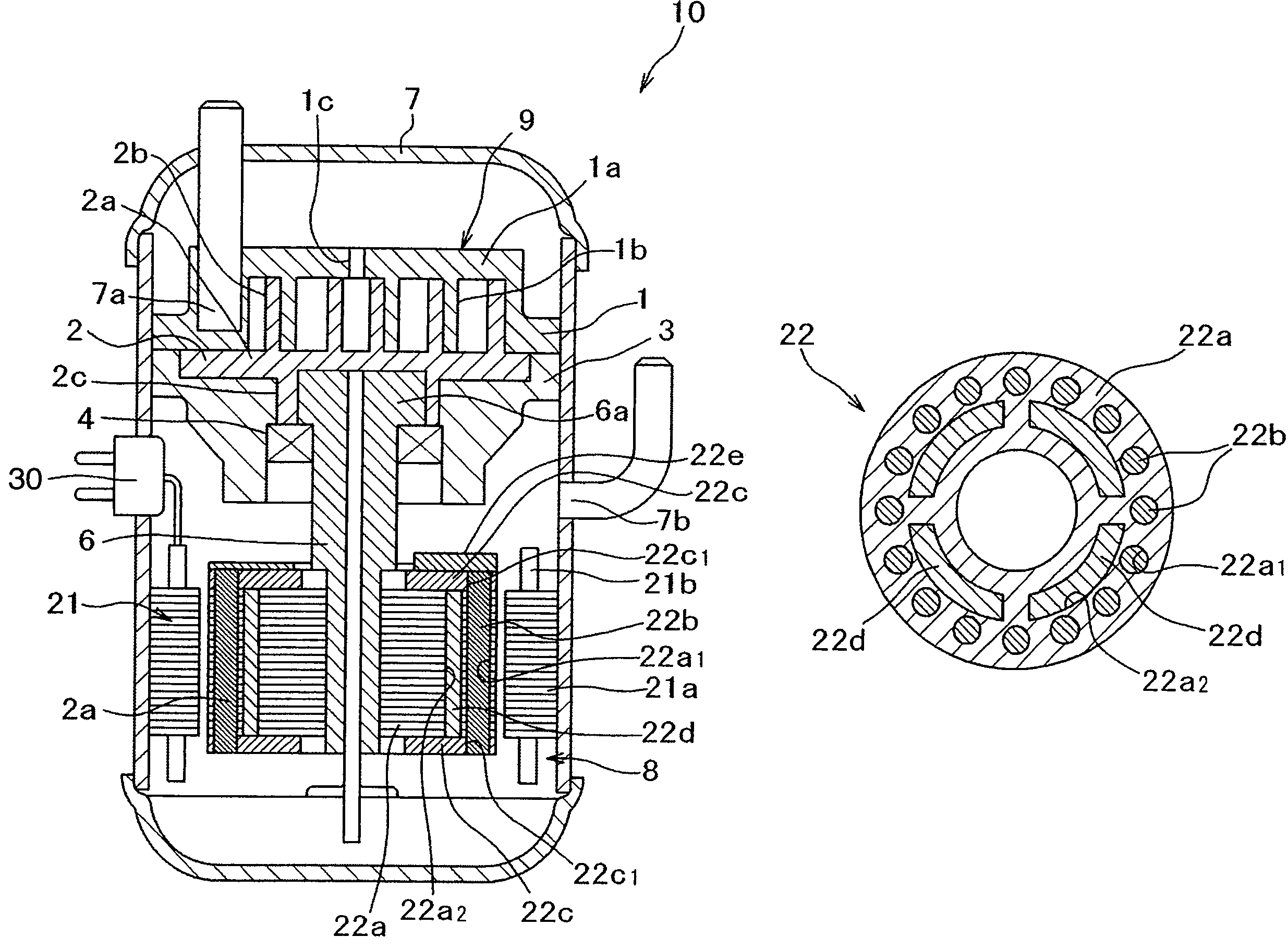
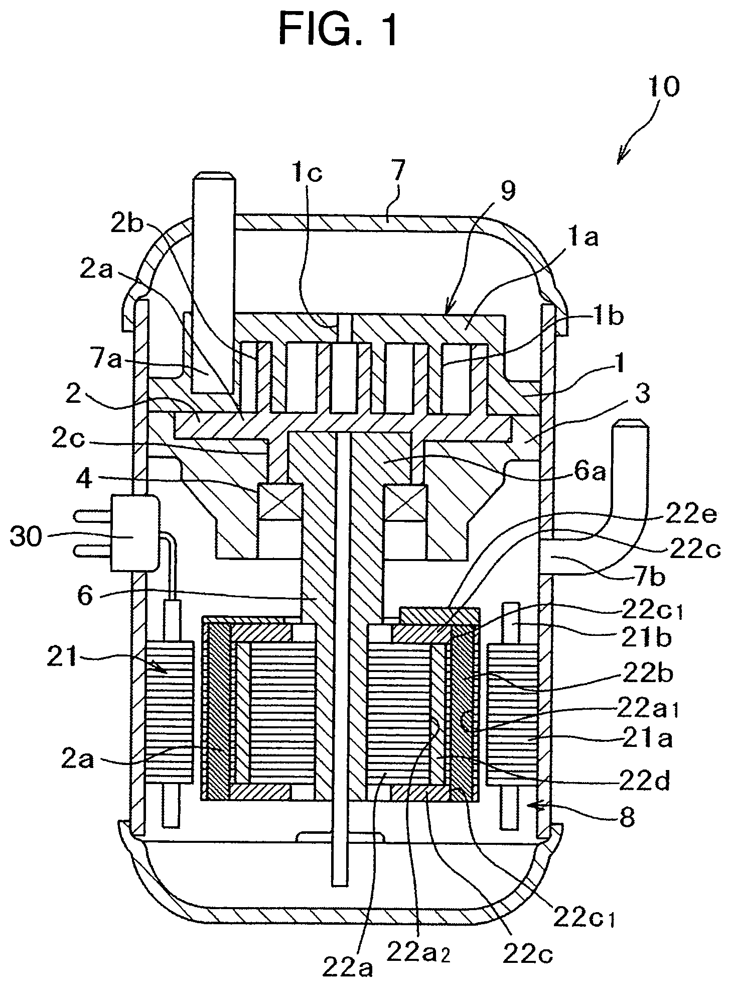
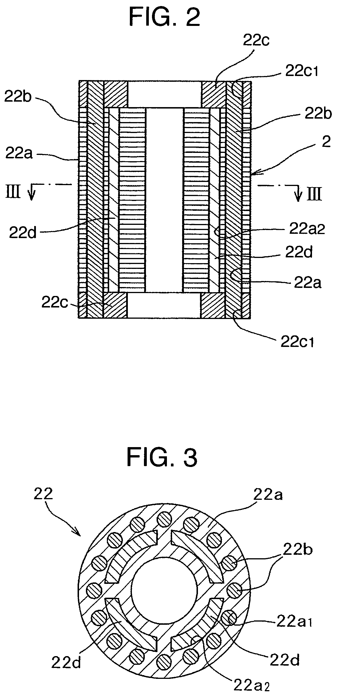
[0037]First, the overall configuration of a compressor 10 in the first embodiment will be explained with reference to FIG. 1. FIG. 1 is a longitudinal sectional view illustrating a compressor incorporating a self-start synchronous motor in the first embodiment.

[0038]A closed container 7 has a sealed structure, enclosing therein a compression mechanism portion 9 composed of a stationary scroll 1, an orbiting scroll 2, a frame 3 and the like, and the self-start synchronous motor 8 composed of a stator 21, a rotor 22 and the like, and a lubricant (which is not shown). The compression mechanism portion 9 and the self-start synchronous motor 8 are arranged up and down. The closed container 7 can bear against a high pressure of compressed fluid (refrigerant gas used for refrigeration c...

second embodiment

[0060]Next, explanation will be made of a second embodiment according to the present invention with reference to FIGS. 5A to 5C. FIGS. 5A to 5C are perspective process views for explaining a method of manufacturing a self-start synchronous motor according to the second embodiment of the present invention. The configuration of the second embodiment is basically the same as that of the first embodiment, except those which will be explained hereinbelow. Thus, explanation duplicated with that of the first embodiment will be omitted.

[0061]In the second embodiment, at first, as shown in FIG. 5a, the conductor bars 22b and one of the end rings 22c are previously integrally incorporated with each other. Then, as shown in FIG. 5B, the conductor bars 22b of the thus integrally incorporated product are inserted through the circular slits 22a1 of the rotor core 22a, allowing the free end portions thereof to project from an end face of the rotor core 22a, and the projected portions of the conduc...

third embodiment

[0064]Next, explanation will be made of a third embodiment according to the present invention with reference to FIG. 6. FIG. 6 is a perspective process view for explaining a method of manufacturing a self-start synchronous motor according to the third embodiment of the present invention. The configuration of the third embodiment is basically the same as that of the first embodiment, except those which will be explained hereinbelow. Thus, explanation duplicated with that of the first embodiment will be omitted.

[0065]In the third embodiment, the conductor bars 22b and end rings 22c are made of copper or copper alloy, and the balance weight portion 22e is integrally incorporated with the end ring 22c by means copper die-casting or copper forging. Further, with the preparation of conductor bars having two different lengths, the end faces of the conductor bars 22b are exposed flush with the outer surface of the balance weight portion 22e and the outer surface of the end ring 22c where th...


PUM


Abstract

In a method of manufacturing a self-start synchronous motor for preventing deterioration of permanent magnets used in a rotor, and also for enhancing the efficiency of the self-start synchronous motor, the self-start synchronous motor comprising a stator having a stator core and windings wound around the stator core, and a rotor having an outer diameter slightly smaller than an inner diameter of the stator and arranged inside of the stator. The rotor is provided with a rotor core, a plurality of conductor bars embedded in the outer peripheral portion of the rotor core over an entire periphery thereof, end rings provided on opposite end sides of the conductor bars and constituting a squirrel cage conductor in cooperation with the conductor bars, and a plurality of permanent magnets embedded in the rotor core and arranged at a position inner than that of an inner peripheral surface of the conductor bars. Further, the conductor bars and the end rings are electrically and mechanically joined together through frictional agitation joint.

Description

INCORPORATION BY REFERENCE[0001]The present application claims priority from Japanese application JP 2005-153698 filed on May 26, 2005, the content of which is hereby incorporated by reference into this application.BACKGROUND OF THE INVENTION[0002]1. Field of the Invention[0003]The present invention relates to a self-start synchronous motor, a method for manufacturing the same and a compressor.[0004]2. Description of Related Art[0005]For example, JP-A-2001-73948 (Patent Document 1) discloses a conventional self-start synchronous motor, which comprises a stator having a stator core and windings wound on the stator core, and a rotor having an outer diameter slightly smaller than that of the inner diameter of the stator and arranged inside of the stator. The rotor is provided with a rotor core, multiple conductor bars circumferentially arranged and embedded in the outer peripheral portion of the rotor core, end rings (short-circuit rings) provided on opposite ends of the conductor bars...

Claims


Application Information

Patent Timeline
Patent Type & Authority Patents(United States)
IPC IPC(8): H02K21/12
CPCB22D19/0054H02K15/0012H02K21/46
Inventor HANG, BAIYINGYOSHIKAWA, TOMIOOHISHI, YASUROTAKAHASHI, AKESHIKOHARAGI, HARUO
Owner HITACHI APPLIANCES INC
Why Eureka
Try Eureka