
Centrifugal turbine blower with gas foil bearings

Inactive Publication Date: 2009-05-19
LASER
View PDF47 Cites 30 Cited by
  • Summary
  • Abstract
  • Description
  • Claims
  • Application Information

AI Technical Summary

Benefits of technology

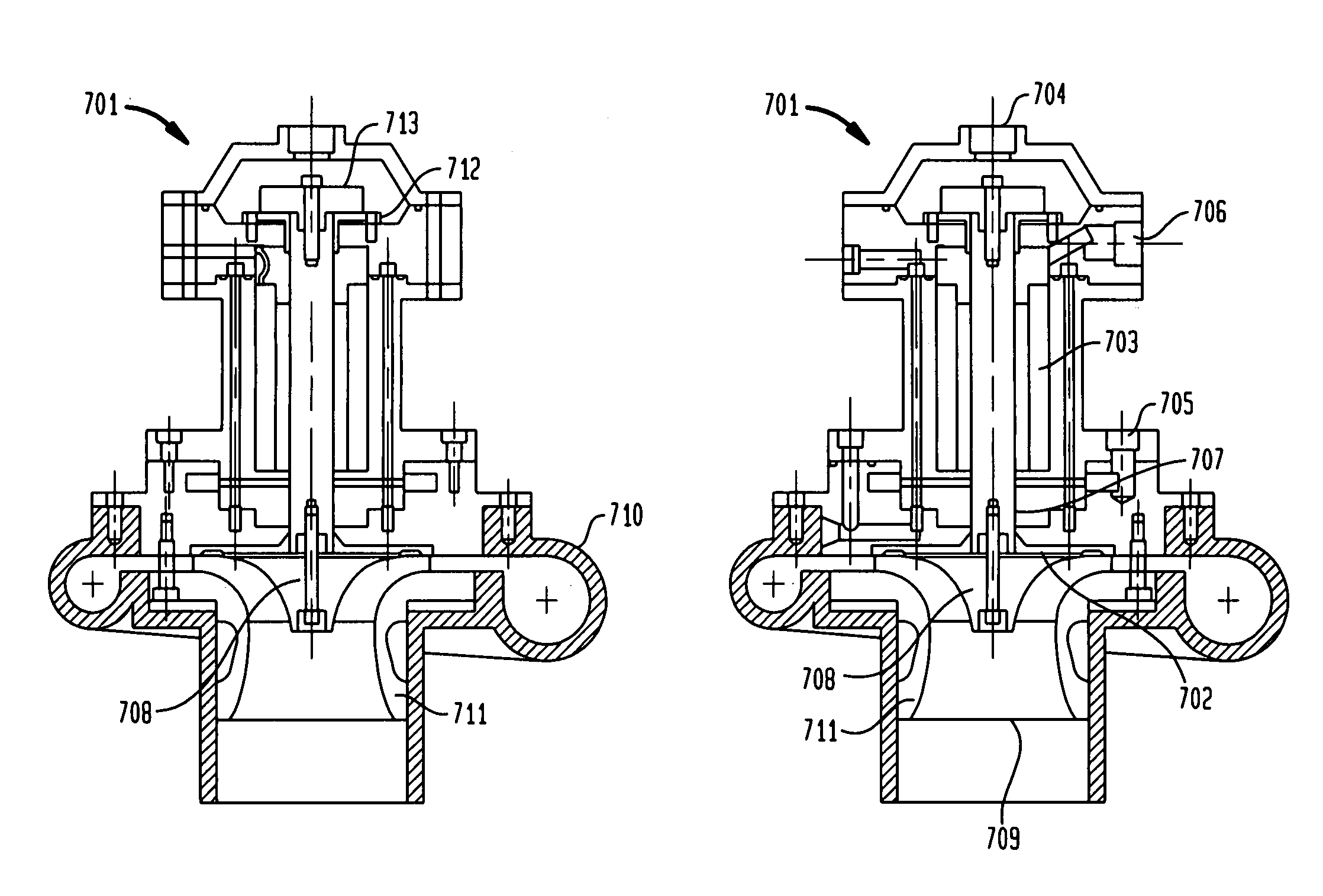
[0014]The present invention provides a centrifugal turbine blower that incorporates foil bearings to provide increased efficiency and functionality of the laser with which it is used, as well as decreased maintenance costs. More specifically, the present invention utilizes a blower with one or more radial foil bearings in order to save energy, reduce the heat load chiller size, lower material costs, and increase overall functionality of the laser system as a whole.
[0015]The blower design of the present invention allows for increased rotational speeds due to the reduced limitations of the bearing design. With a non-contact, self-lubricating foil bearing, a single unit blower is configured for lasers up to 8 kilowatts (kW). In addition, the blower re-circulates the flow gas from the laser (around 10-15%), which cools the bearings and motor allowing for the potential use of an AC motor in place of the DC motor which is currently utilized in most systems.
[0016]Another embodiment of the present invention allows for variable compressor size dependent on the laser flow requirements. This allows for peak efficiencies of different combinations of impellers, diffusers, shrouds and covers between 3 kW and 8 kW. The blower in accordance with the present invention is designed with a bypass load and variable speeds through its variable compressor design in order to avoid surge conditions during laser operation. The variable blower allows for the motor, bearings and housing to remain unaltered. As a result, the internal combination of the impeller, diffuser and shroud determine the output. This allows for variable speed control in order to balance the gas conditions within the system.

Problems solved by technology

However, a regenerative compressor is quite inefficient, achieving only 35% pump efficiency.
Unlike the regenerative system, however, the radial system is difficult to maintain.
However, the principal disadvantage with such a system is that it cannot operate at peak efficiency for the impeller, because the bearings are limited by both speed and load capacity.
For instance, the magnetic blower is very expensive and contains very complex bearing control units.
Further, an active magnetic bearing needs a redundant bearing system in the event of power failure, which results in a loss of magnetizing power.
These conditions, however, do not allow complete freedom of design.
However, a majority of the current blowers are not designed to properly handle a foil bearing, and cannot reach the higher rotational speeds necessary for optimum pumping efficiency.
In addition, efficiency and power consumption depend greatly on the blower functionality within the system.
If the system is not properly cooled and / or heated, then it will not function at maximum efficiency.
If the blower is more efficient, overall waste heat and power consumption drops dramatically.
As previously discussed, bearing design has a significant affect on the maintenance of the blower.
If the bearings wear easily, they must be replaced more often.

Method used


Image

  • Centrifugal turbine blower with gas foil bearings
  • Centrifugal turbine blower with gas foil bearings
  • Centrifugal turbine blower with gas foil bearings

Examples


Embodiment Construction

[0037]As required, a detailed illustrative embodiment of the present invention is disclosed herein. However, techniques, systems, and operating structures in accordance with the present invention may be embodied in a wide variety of sizes, shapes, forms and modes, some of which may be quite different from those in the disclosed embodiment. Consequently, the specific structural and functional details disclosed herein are merely representative, yet in that regard, they are deemed to afford the best embodiment for purposes of disclosure and to provide a basis for the claims herein, which define the scope of the present invention.

[0038]The following presents a detailed description of the preferred embodiment of the present invention, as well as some alternate embodiments of the invention. Reference is herein made to the figures, wherein the numerals representing particular parts are consistently used throughout the figures and accompanying discussion.

[0039]Referring to Table 1, depicted...


PUM


Abstract

Disclosed is a centrifugal turbine gas blower with foil bearings for use with a fast axial flow laser. The blower utilizes variable components in order to operate at different speeds for multiple applications. In addition, a bypass load has been incorporated to avoid a surge condition. The blower utilizes foil bearings that are self-lubricating in order to achieve improved efficiency and maximized speeds during operation. The bearings are designed with a bump layer that provides damping for pre-load. Additionally, the backplate of the thrust assembly contains holes in order to reduce the thrust load and to balance the force on the impeller.

Description

FIELD OF INVENTION[0001]The present invention relates generally to gas circulation blowers for lasers. More specifically, the present invention relates to a centrifugal turbo gas blower which utilizes one or more foil bearings in combination with one or more Carbon Dioxide (“CO2”) lasers.BACKGROUND[0002]Each component in the design of a laser system is important for the proper functionality of a system as a whole. In particular, the design of an axial flow CO2 laser must contain a gas circulation blower to ensure the performance of the device. The systems' blower has to circulate gases at high velocities through the laser's active plasma region to maintain efficient operation and provide stable laser output power.[0003]There are a variety of gas circulation blowers, or compressors, available for use with the CO2 laser system. Each design has advantages and disadvantages for the specific use and performance of the overall system. Current gas blowers include the regenerative (side-cha...

Claims


Application Information

Patent Timeline
IPC IPC(8): H02K17/00
CPCF04D29/056F16C17/024H02K7/083F16C2360/24F16C17/042
Inventor WILSON, WALTER
Owner LASER
Learn More