Circuit arrangement and method for supplying power to a transponder

a transponder and circuit technology, applied in vehicle tyre testing, instruments, roads, etc., can solve the problems of affecting the reliability of data transmission, the distance within which reliable data and energy transmission is possible, and the frequency-detuning effect changing the resonance frequency of the antenna resonant circuit, etc., to achieve rapid charging

Active Publication Date: 2009-05-19
ATMEL CORP
View PDF23 Cites 24 Cited by
  • Summary
  • Abstract
  • Description
  • Claims
  • Application Information

AI Technical Summary

Benefits of technology

[0014]It is therefore an object of the present invention to provide as rapid a charging as possible particularly of a transponder equipped with a large charging capacitor.
[0019]To tune the antenna resonant circuit, it is not necessary to wait until the charging capacitor is charged. Rather, according to the invention, this antenna resonant circuit is tuned in terms of time before the charging of the charging capacitor, so that the charging capacitor can then be charged with an optimal charging current. The voltage for tuning the antenna resonant circuit is thereby provided by an auxiliary voltage source, which is preferably formed as an auxiliary capacitor. The charging of the charging capacitor thus occurs in each case with a tuned antenna resonant circuit, so that the charging current becomes maximal and the charging time for charging the charging capacitor minimal. The present invention thereby allows a multistage power management for time-optimized charging of the charging capacitor.

Problems solved by technology

The problem arises in practice that frequency-detuning effects change the resonance frequency of the antenna resonant circuit of the transponder.
It is problematic here that their coupling relationships then worsen, as a result of which even with minor detuning of the resonant circuit, the distance within which reliable energy and data transmission is possible declines considerably.
If the resonance frequency of the resonant circuit is outside this tolerance range, reliable data and energy transmission is no longer possible.
Nevertheless, for some transponder applications, such as, for example, the aforementioned tire pressure control systems, there is need for a relatively large charging capacitor and thereby a high supply voltage.
However, a considerably lower charging current results if the transponder and its antenna resonant circuit are not tuned to the resonance frequency.
Because of the lower antenna current, it takes significantly longer to charge the charging capacitor of the transponder.
This has the result that the corresponding transponder does not have its assigned function and thereby is not able to fulfill its task.
The problem in tuning the transponder resonant circuit now is to provide as rapidly as possible a voltage to tune the antenna resonant circuit.
If the antenna resonant circuit is detuned, however, the charging of the charging capacitor takes very long, so that a voltage for tuning becomes available only very late.

Method used


Image

  • Circuit arrangement and method for supplying power to a transponder
  • Circuit arrangement and method for supplying power to a transponder
  • Circuit arrangement and method for supplying power to a transponder

Examples


Embodiment Construction

[0043]In the figures of the drawing, the same and functionally identical elements and signals, if not specified otherwise, are provided with the same reference characters.

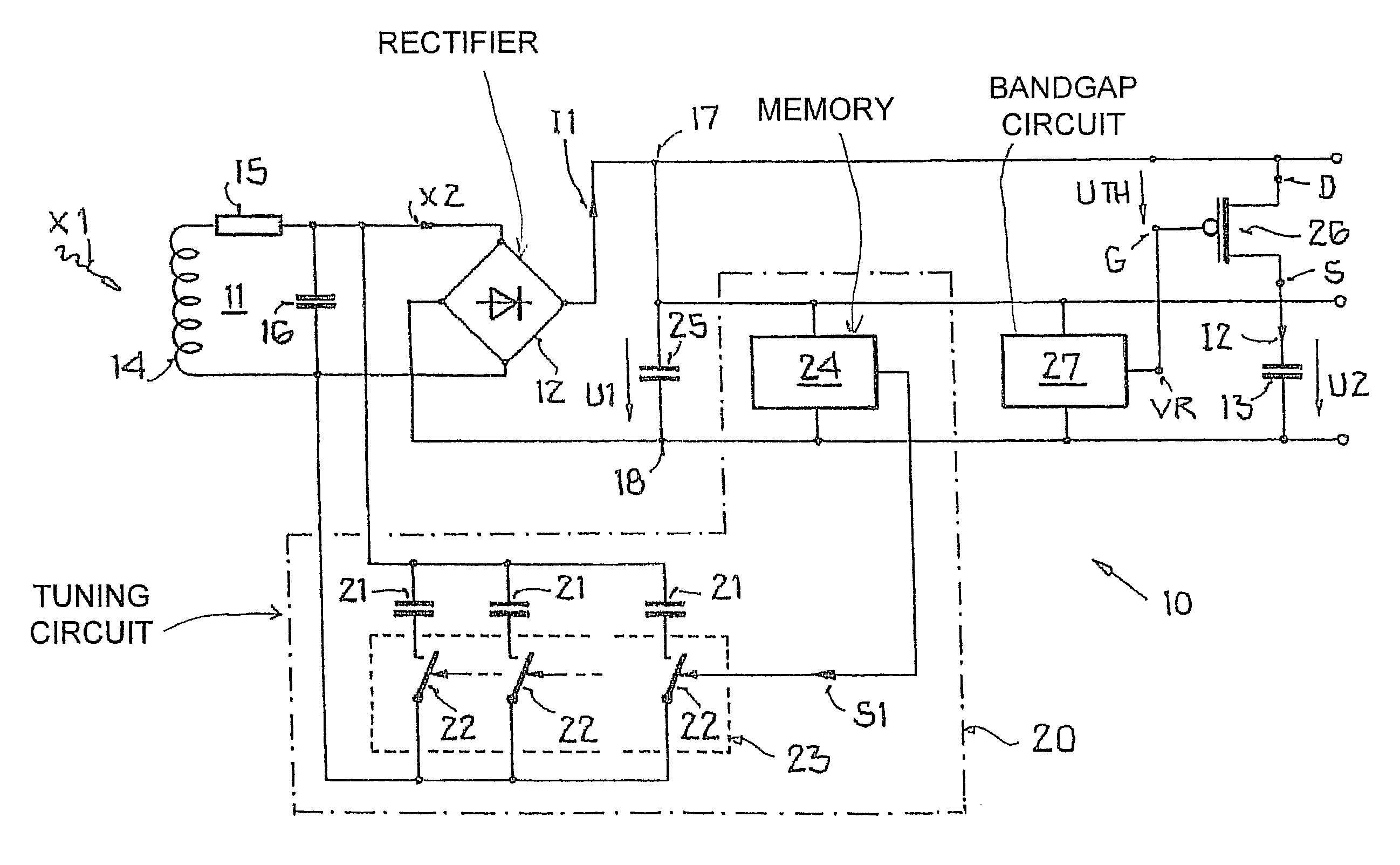
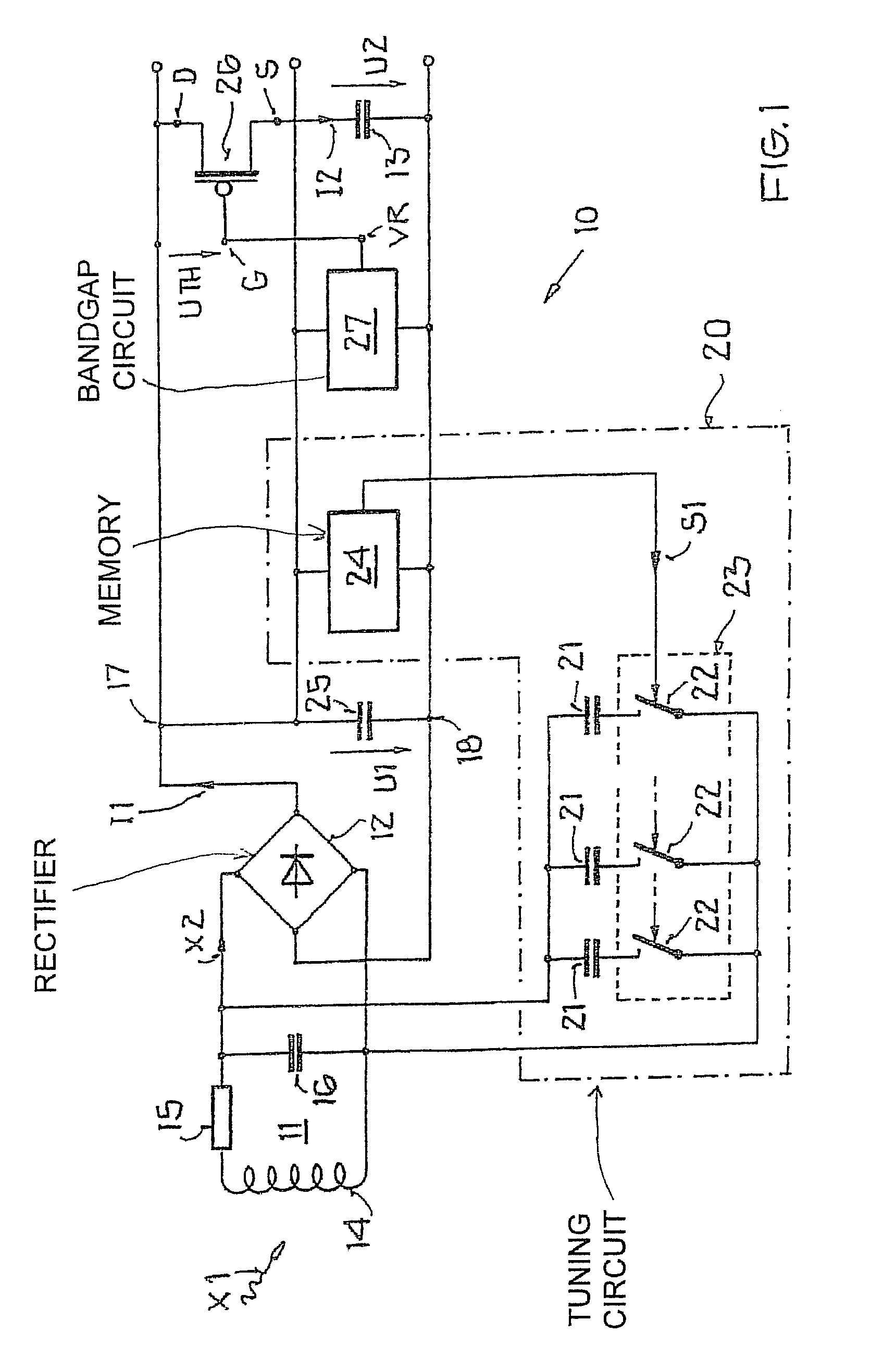
[0044]FIG. 1 shows a first, especially preferred exemplary embodiment of a circuit arrangement of the invention. In this connection, FIG. 1 shows only the receiving path of a transponder (not shown) for a tire pressure control system.

[0045]In FIG. 1, the circuit arrangement of the invention for the power supply to the transponder is identified with the reference character 10. The circuit arrangement 10 has on the receiving side an antenna resonant circuit 11, with a downstream rectifier circuit 12 and a charging capacitor 13, which is also called a backup capacitor.

[0046]The antenna resonant circuit 11 has an inductive antenna 14, which is concisely called an antenna coil 14 hereafter, and a resistive element 15 assigned in series thereto, for example, a resistor 15. The antenna coil 14 has the function of picking ...


PUM


Abstract

A circuit arrangement is provided for a power supply to a transponder including an antenna resonant circuit and a downstream rectifier circuit for receiving and for rectifying an electromagnetic signal, a charging capacitor connected downstream on the output side of the rectifier circuit to provide a first supply voltage, with a tuning circuit for tuning the antenna resonant circuit to its resonance frequency, and with an auxiliary voltage source, which is designed to provide a second supply voltage, lower than the first supply voltage, for supplying the tuning circuit. A method is also provided for supplying power to a transponder with a first supply voltage, as well as a transponder having a circuit arrangement for a power supply.

Description

[0001]This nonprovisional application claims priority under 35 U.S.C. § 119(a) on German Patent Application No. DE 102005005812, which was filed in Germany on Feb. 9, 2005, and which is herein incorporated by reference.BACKGROUND OF THE INVENTION[0002]1. Field of the Invention[0003]The present invention relates to a circuit arrangement for power supply to a transponder, a method for supplying power to a transponder with a first supply voltage, and to a transponder having a circuit arrangement for a power supply.[0004]2. Description of the Background Art[0005]The invention falls within the realm of transponder technology and in particular within the field of contactless communication. Although usable in principle in any communication systems, the present invention and its underlying problem are explained hereafter with reference to transponders for tire pressure control systems and the applications thereof. For a general background of transponder technology, reference is made to the ...

Claims


Application Information

Patent Timeline
Patent Type & Authority Patents(United States)
IPC IPC(8): G08B13/14
CPCG06K19/0701G06K19/0726G06K19/07749
Inventor MOSER, DANIELMOSER, HELMUT
Owner ATMEL CORP
Why Eureka
Try Eureka