Magnetoresistive head with improved in-stack longitudinal biasing layers and fabricating method

a magnetic head and longitudinal biasing technology, applied in the field of magnetic heads, can solve the problems of affecting the symmetry of the reading waveform, reducing the reading sensitivity, and unable to obtain reading characteristics, so as to achieve convenient alignment, suppress barkhausen noise, and high reading sensitivity

Inactive Publication Date: 2009-05-19
WESTERN DIGITAL TECH INC
View PDF36 Cites 7 Cited by
  • Summary
  • Abstract
  • Description
  • Claims
  • Application Information

AI Technical Summary

Benefits of technology

[0014]It is a feature of the present invention to provide a method for easily controlling the magnetization direction of a layer applying a longitudinal biasing field to the pinned layer and the free layer in a magnetoresistive head having a longitudinal biasing method in lieu of a hard-bias.
[0018]At least one of the magnetic layers constituting the pinned layer may be composed of a hard magnetic material. Additionally, the saturation magnetic flux density and the film thickness of each magnetic layer constituting the pinned layer are controlled to make the substantial magnetic moment almost zero when the magnetization of each magnetic layer constituting the pinned layer is aligned in an antiparallel manner. As a result, the magnetization of the pinned layer does not easily reverse or rotate in response to the external field, and the magnetization direction can be substantially pinned. Forming a pinned layer while applying a magnetic field in a desired direction (that is, a direction perpendicular to the magnetic recording medium) and inducing uniaxial magnetic anisotropy makes it possible to control the magnetization direction of the pinned layer.
[0021]It is preferable to induce uniaxial magnetic anisotropy applying a field in track width direction in the case of forming the free layer and the longitudinal biasing layer. The longitudinal biasing layer pins the magnetization direction in the track width direction by magnetic exchange coupling with the antiferromagnetic layer. At the edge of the track width direction of the magnetoresistive sensor, a longitudinal biasing field is applied in the track width direction by return of magnetic flux essentially from the longitudinal biasing layer to the free layer. Additionally, the effect can be enhanced by antiferromagnetically coupling the free layer and longitudinal biasing layer through the nonmagnetic separate layer. Since the magnitude of the longitudinal biasing field can be arbitrarily changed by selecting the magnetic moment of the longitudinal biasing layer and the material and film thickness of the nonmagnetic layer, it is possible to easily reconcile high reading sensitivity and suppressed Barkhausen noise. Moreover, materials and film thicknesses, which have a large magnetic exchange coupling with excellent thermal stability, are preferably adopted for the antiferromagnetic layer.
[0023]During the annealing process in a magnetic field, there is a possibility that the magnetization of the pinned layer is shifted from a desired direction, but the magnetization direction of the pinned layer can be aligned in the direction perpendicular to the magnetic recording medium by applying a magnetic field at room temperature after completing the annealing process. Even if the magnetization direction of the pinned layer is shifted from the direction perpendicular to the magnetic recording medium, it can be restored to the direction perpendicular to the magnetic recording medium by applying a static field at room temperature. The important thing herein is that it is possible to control the magnetization direction of the pinned layer to be in a desired direction even if a special treatment such as an annealing process in a magnetic field is not applied. That is, a step determining the magnetization direction of the pinned layer does not affect the magnetization direction of the free layer and the longitudinal biasing layer which applies a longitudinal biasing field to the free layer. Therefore, the magnetization directions of the pinned layer and the longitudinal biasing layer which applies a longitudinal biasing field to the free layer can be easily aligned in an orthogonal direction without interfering with each other.
[0024]Embodiments of the present invention achieve control of the magnetization direction of the pinned layer and a layer which applies a longitudinal biasing field to the free layer, and provide a magnetoresistive head and a manufacturing method thereof which can accomplish high reading sensitivity, suppression of Barkhausen noise, and excellent symmetry of a reading waveform even if there is progress in narrowing the track width.

Problems solved by technology

In the future, because of the reasons described above, one expects that reconciling guaranteed reading sensitivity and suppressed Barkhausen noise may become difficult to achieve in a hard-bias structure by progressive narrowing of the track width with increasing longitudinal recording density of magnetic recording systems.
That is, in a hard-bias structure, it is virtually impossible to obtain reading characteristics which can be used for future magnetic recording devices with high recording density; therefore it is necessary to establish a new longitudinal biasing method.
On the other hand, in an alternate longitudinal biasing method which is currently being proposed, controlling the magnetization direction of the layer applying a longitudinal biasing field to the pinned layer and free layer is difficult, thereby problems may arise such as decreased reading sensitivity and affected symmetry of the reading waveform.
It is a common problem not only for next generation magnetoresistive heads such as a current CIP (Current in the plane)-GMR head, but also for a TMR (Tunneling Magnetoresistive) head and a CPP (Current perpendicular to the plane)-GMR head which are expected to be used in practice.

Method used


Image

  • Magnetoresistive head with improved in-stack longitudinal biasing layers and fabricating method
  • Magnetoresistive head with improved in-stack longitudinal biasing layers and fabricating method
  • Magnetoresistive head with improved in-stack longitudinal biasing layers and fabricating method

Examples


first embodiment

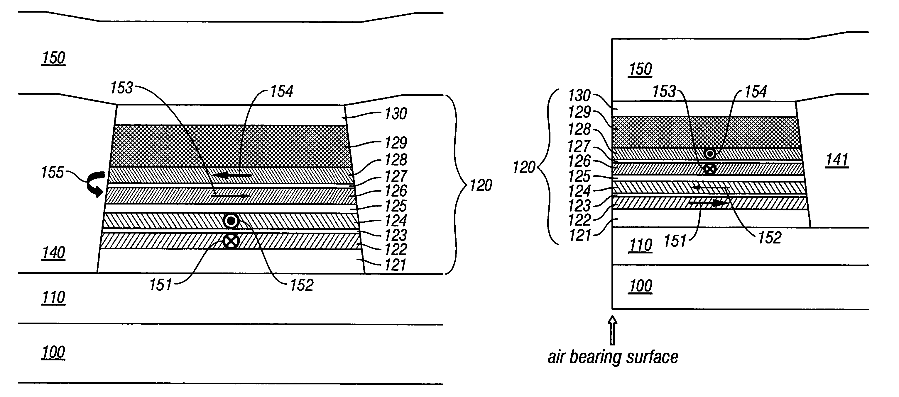
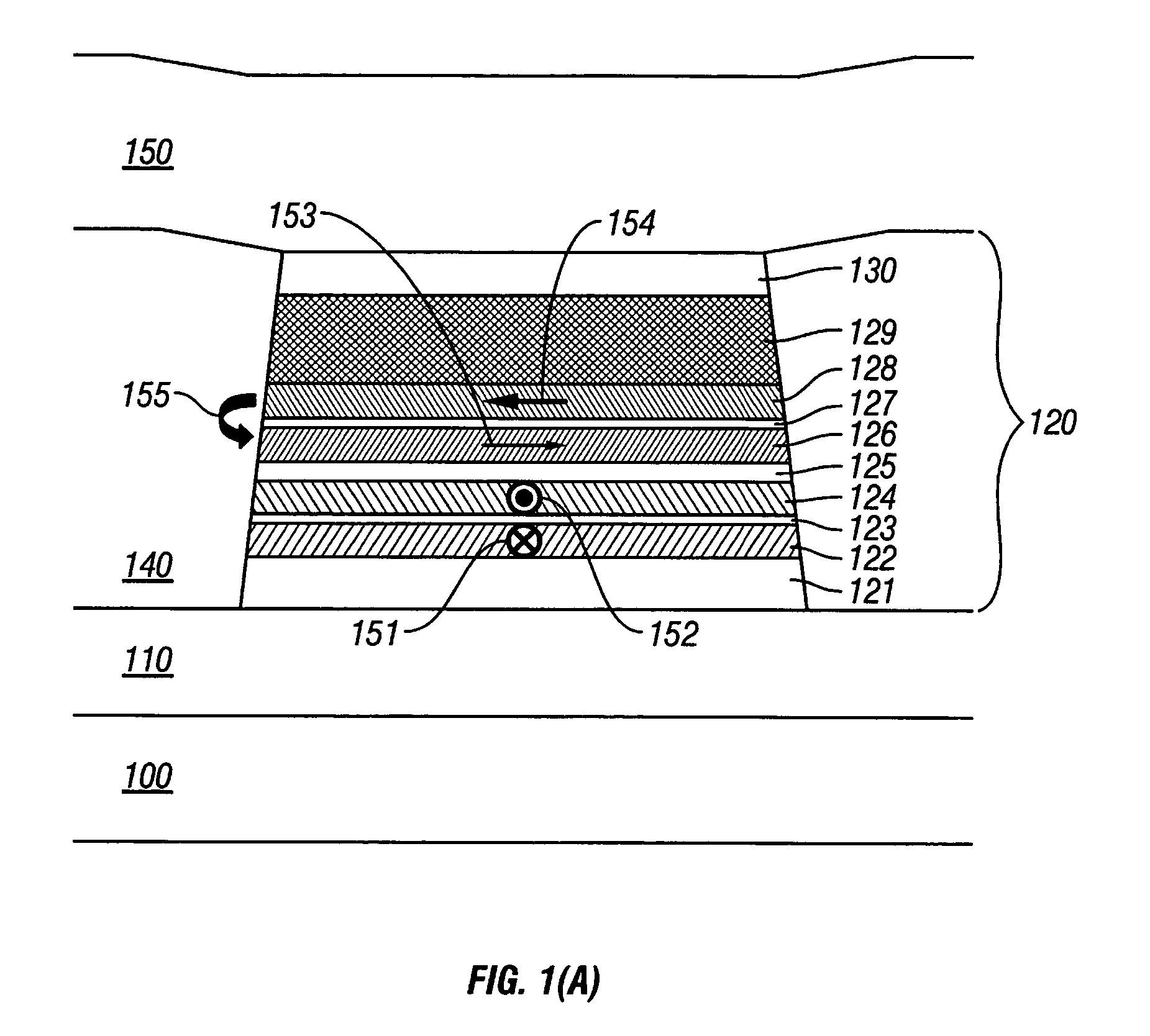
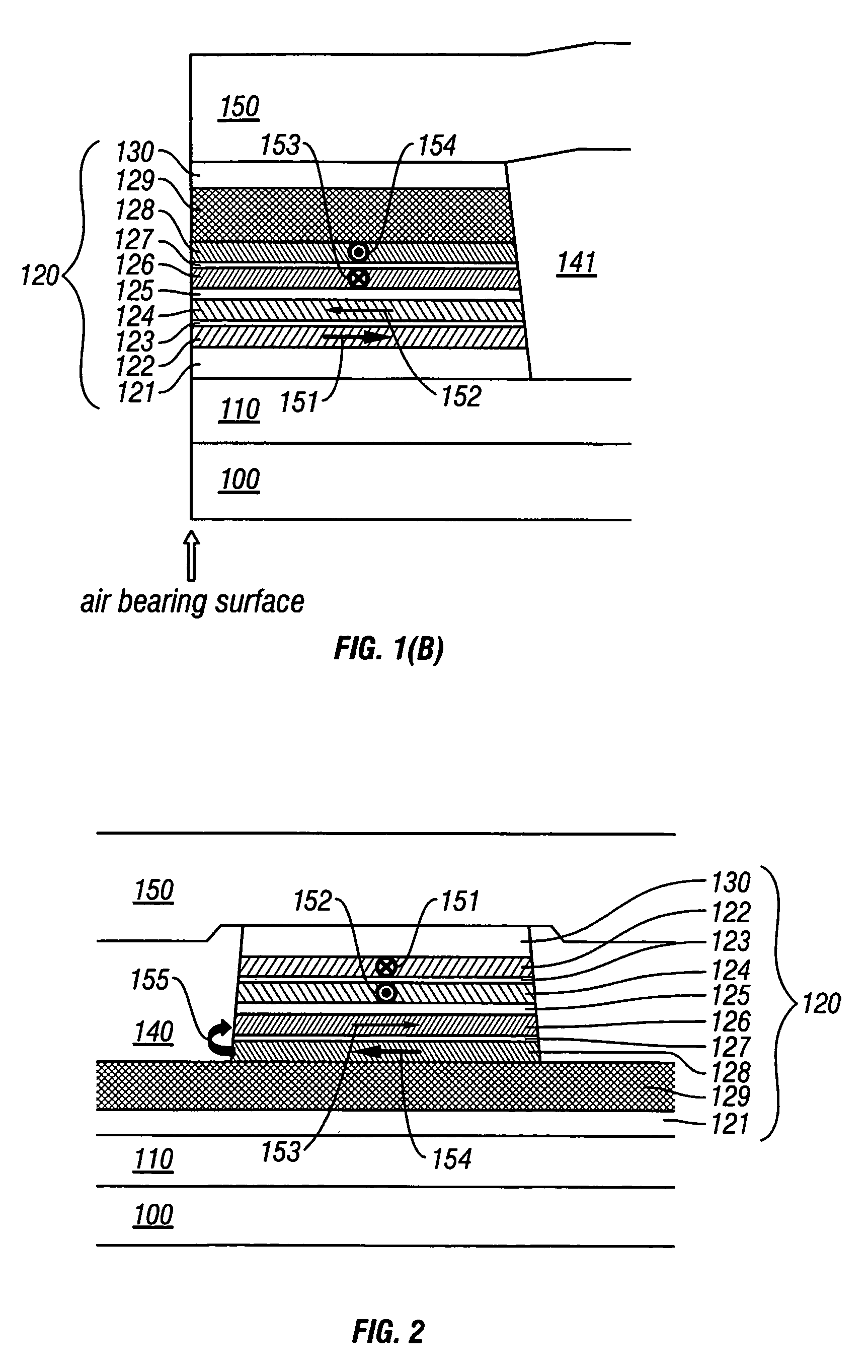
[0048]FIG. 1 is a schematic diagram illustrating the first embodiment of a magnetoresistive head of the present invention. FIG. 1(A) is a schematic diagram seen from the air bearing surface, and FIG. 1(B) is a cross-section at the track center in the sensor height direction (a direction perpendicular to the magnetic recording medium). The structure together with an outline of the fabricating procedure of a magnetoresistive head will be described below.

[0049]A magnetoresistive film 120 is formed on a substrate 100 after forming a lower shield 110, and the track width direction is patterned into a desired shape by photolithography, ion milling, or reactive ion etching. Next, an insulator layer 140 is formed at both sides of the magnetoresistive film 120 using a lift-off method. Similarly, in the sensor height direction, the magnetoresistive film 120 is patterned into a desired shape by photolithography, ion milling, or reactive ion etching, and an insulator layer 141 is formed using a...

second embodiment

[0054]FIG. 2 is a schematic diagram illustrating the second embodiment of a magnetoresistive head of the present invention when seen from the air bearing surface. The cross-section at the track center in the sensor height direction is omitted because it is the same as the first embodiment.

[0055]In the first embodiment, a configuration was shown as an example in which the pinned layer is formed on a side close to the substrate 100 in the magnetoresistive layer 120. On the other hand, in the second embodiment, the order of lamination is reversed as the primary layer 121 / antiferromagnetic layer 129 / longitudinal biasing layer 128 / nonmagnetic layer 127 / magnetic free layer 126 / nonmagnetic conductive layer or nonmagnetic tunneling barrier layer 125 / second magnetic layer 124 / antiferromagnetic coupling layer 123 / first magnetic layer 122 / protection layer 130. Additionally, the primary layer 121 / antiferromagnetic layer 129 are not etched in the track width dimension, and they are patterned wid...

third embodiment

[0074]FIG. 8 is a schematic diagram illustrating the third embodiment of a magnetoresistive head of the present invention when seen from the air bearing surface. The basic configuration is the same as the second embodiment so that the details are omitted.

[0075]In this embodiment, the configuration of the pinned layer is fourth magnetic layer 134 / third antiferromagnetic coupling layer 133 / third magnetic layer 132 / second antiferromagnetic coupling layer 131 / first magnetic layer 122 / first antiferromagnetic coupling layer 123 / second magnetic layer 124. Symbols 156 and 157 in the figure indicate the magnetization direction of the third magnetic layer and the magnetization direction of the fourth magnetic layer, respectively. In the first and second embodiments, the configuration of the pinned layer included two magnetic layers. But, when the configuration contains more than three magnetic layers as, for instance, in Co—Fe / Ru / Co—Fe and the third embodiment, the magnetization direction is ...


PUM

PropertyMeasurementUnit
thicknessaaaaaaaaaa
thicknessaaaaaaaaaa
coercivity Hcaaaaaaaaaa

Abstract

A magnetoresistive head and a fabricating method thereof accomplishing high sensitivity and low noise are provided even if track width narrowing makes progress. In one embodiment, a pinned layer includes a laminate which includes at least two magnetic layers and where adjacent magnetic layers are coupled antiferromagnetically to each other, and a mechanism to apply a longitudinal biasing field to a free layer is made to function by laminating a nonmagnetic separate layer / longitudinal biasing layer / antiferromagnetic layer connecting the free layer and opposite a nonmagnetic conductive layer (or nonmagnetic tunneling barrier layer). Controlling a magnetization direction of the longitudinal biasing layer which bears application of a longitudinal biasing field to the pinned layer and free layer is achieved by annealing carried out while applying a magnetic field in a track width direction and applying a magnetic field at room temperature.

Description

CROSS-REFERENCES TO RELATED APPLICATIONS[0001]This application claims priority from Japanese Patent Application No. JP2004-016126, filed Jan. 23, 2004, the entire disclosure of which is incorporated herein by reference.BACKGROUND OF THE INVENTION[0002]This invention relates to a magnetic head mounted in a magnetic recording system, more specifically to a magnetoresistive head and a fabricating method thereof to read information recorded on a magnetic recording medium.[0003]Recently, a GMR (Giant Magnetoresistive) head using a so-called “spin valve”, which has a basic configuration consisting of magnetic layer / nonmagnetic conductive layer / magnetic layer / antiferromagnetic layer as written in JP-A 358310 / 1992, has been widely adopted for a magnetoresistive head mounted in a magnetic recording system as a read sensor. In the spin valve, a magnetic film in which the magnetization direction is pinned in one direction by magnetic exchange coupling with an antiferromagnetic film is called a...

Claims


Application Information

Patent Timeline
Patent Type & Authority Patents(United States)
IPC IPC(8): G11B5/39G11B5/127G11B5/33H01F10/32H01L43/08
CPCG11B5/3912G11B5/3932
Inventor MEGURO, KENICHINISHIOKA, KOUICHIHATATANI, MASAHIKOHAGINOYA, CHISEKI
Owner WESTERN DIGITAL TECH INC
Why Eureka
Try Eureka