Wind velocity measuring device and electronic apparatus

a technology of wind velocity and measuring device, which is applied in the direction of domestic cooling apparatus, lighting and heating apparatus, instruments, etc., can solve the problems of difficult to measure the wind velocity of air with high precision, various controls cannot be performed on the basis of wind velocity, and the inability to accurately detect the blockage of the filter. , to achieve the effect of high precision and accurate detection of the blockag

Inactive Publication Date: 2009-05-19
SEIKO EPSON CORP
View PDF18 Cites 17 Cited by
  • Summary
  • Abstract
  • Description
  • Claims
  • Application Information

AI Technical Summary

Benefits of technology

[0013]According to this structure, the wind velocity measuring device includes the air circulating unit where the barrier portions and the exhaust port are formed. As a result, the air that propagates toward the air circulating unit collides with the barrier portions, and then flows into a space (hereinafter, referred to as internal space) between the barrier portions and the exhaust port. For this reason, in a state where a pressure of a space (hereinafter, referred to as external space) at the front stage side of the passage of air that flows into the air circulating unit is set to be lower than a pressure of the barrier portion, the air can be flown into the internal space. Further, by using the exhaust port, it is possible to increase a flow rate of the air that circulates in the inner space. Accordingly, the pressure of the inner space becomes a pressure sufficiently lower than the pressure of the external space, and the air can be circulated at a predetermined wind velocity in the inner space. In addition, the wind velocity measuring unit measures a wind velocity of the air in the inner space. In terms of a wind velocity measuring characteristic, the wind velocity measuring unit can measure the wind velocity in an optimal pressure state, and can accurately measure a wind velocity of the air blown to the cooled object without causing a variation in the measured wind velocity value.
[0018]In this case, when the usage environment temperature of the electronic apparatus is high, the temperature of the air blown to the cooled object is high, which increases a temperature rising rate in the cooled object (increases an inner temperature rising rate in the exterior casing). Further, when the filter causes clogging, that is, when dusts are attached to the filter and a predetermined amount of air cannot be introduced in the exterior casing, the temperature rising rate in the cooled object is increased. In this case, if the fan driving control unit performs fan control, an increasing rate of a voltage applied to the cooing fans is relatively increased according to the increase in the inner temperature of the exterior casing, and the cooling fans are driven with a set upper limit (upper limit of a usage voltage of the cooling fans).
[0022]As such, the control device can detect the clogging of the filter on the basis of the wind velocity value measured by the wind velocity measuring device with high precision. Accordingly, for example, after the clogging of the filter is detected, the control device performs control that allows a notifying unit to notify information urging the filter exchange, such that a user properly recognizes the filter exchange. Further, for example, after the filter clogging is detected, the control device performs control that allows predetermined constituent members (a light source, a power supply, or the like) to be turned off (driving stop). Therefore, a life span of the electronic apparatus can be lengthened without the constituent elements of the electronic apparatus being damaged due to the heat.
[0024]According to this structure, the wind velocity measuring device is disposed such that the air circulating unit communicates with the inner portions of the ducts. That is, the wind velocity measuring device is disposed on the front stage side of the air passage with respect to the cooled objects. In this way, for example, as compared with the structure where the wind velocity measuring device measures the wind velocity of the air having passed through the cooled objects, the measured wind velocity value can be further suppressed from varying, and the wind velocity of the air blown to the cooled objects can be measured with high precision. Further, when the space in the duct (the external space) has a relatively higher internal pressure than the pressure of the air blown from the cooling fan, the pressure of the internal space of the air circulating unit can be sufficiently lowered by the barrier portion. For example, the internal space can be made to have substantially the same pressure as the arrangement locations of the cooled objects, and the wind velocity of the air blown to the cooled objects can be measured with high precision.
[0026]According to this structure, the projector is used as the electronic apparatus that can accurately detect the clogging of the filter on the basis of the wind velocity value that has been measured with high precision, as described above. For example, after the filter clogging is detected, the control device performs control that allows predetermined constituent members (a light source, a power supply, or the like) to be turned off (driving stop). As a result, without causing a state where the constituent member, such as the light modulating device, is overheated due to irradiation of the light beam to thus be damaged, the projection image from the projector can be viewed by the user, which does not give the user an unpleasant feeling.

Problems solved by technology

That is, the wind velocity of the air cannot be measured with high precision, and thus various controls cannot be performed on the basis of the wind velocity.
Further, even when the protection device including the wind velocity sensor is disposed on a front stage side of an air passage with respect to the liquid crystal panel to be the cooled object, it is difficult to measure a wind velocity of air with high precision due to an influence from a pressure of air blown by the cooling fan.
Further, various controls cannot be performed on the basis of the wind velocity.
Further, when the filter causes clogging, that is, when dusts are attached to the filter and a predetermined amount of air cannot be introduced in the exterior casing, the temperature rising rate in the cooled object is increased.

Method used


Image

  • Wind velocity measuring device and electronic apparatus
  • Wind velocity measuring device and electronic apparatus
  • Wind velocity measuring device and electronic apparatus

Examples


Embodiment Construction

[0040]Hereinafter, an embodiment of the invention will be described with reference to the accompanying drawings.

External Structure of Projector

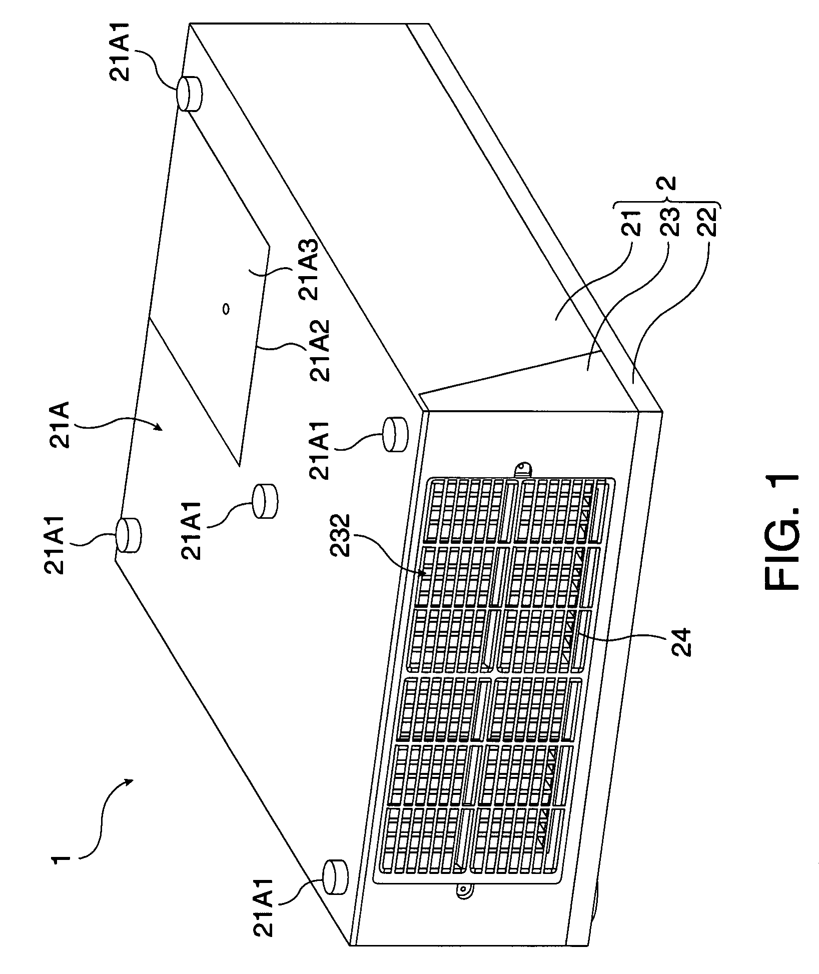
[0041]FIG. 1 is a perspective view illustrating an outer shape of a projector 1 that serves as an electronic apparatus according to an embodiment of the invention.

[0042]The projector 1 according to the embodiment of the invention modulates a light beam emitted from a light source provided in the projector 1 according to image information so as to form an optical image, and projects the optical image onto a screen or the like so as to be enlarged.

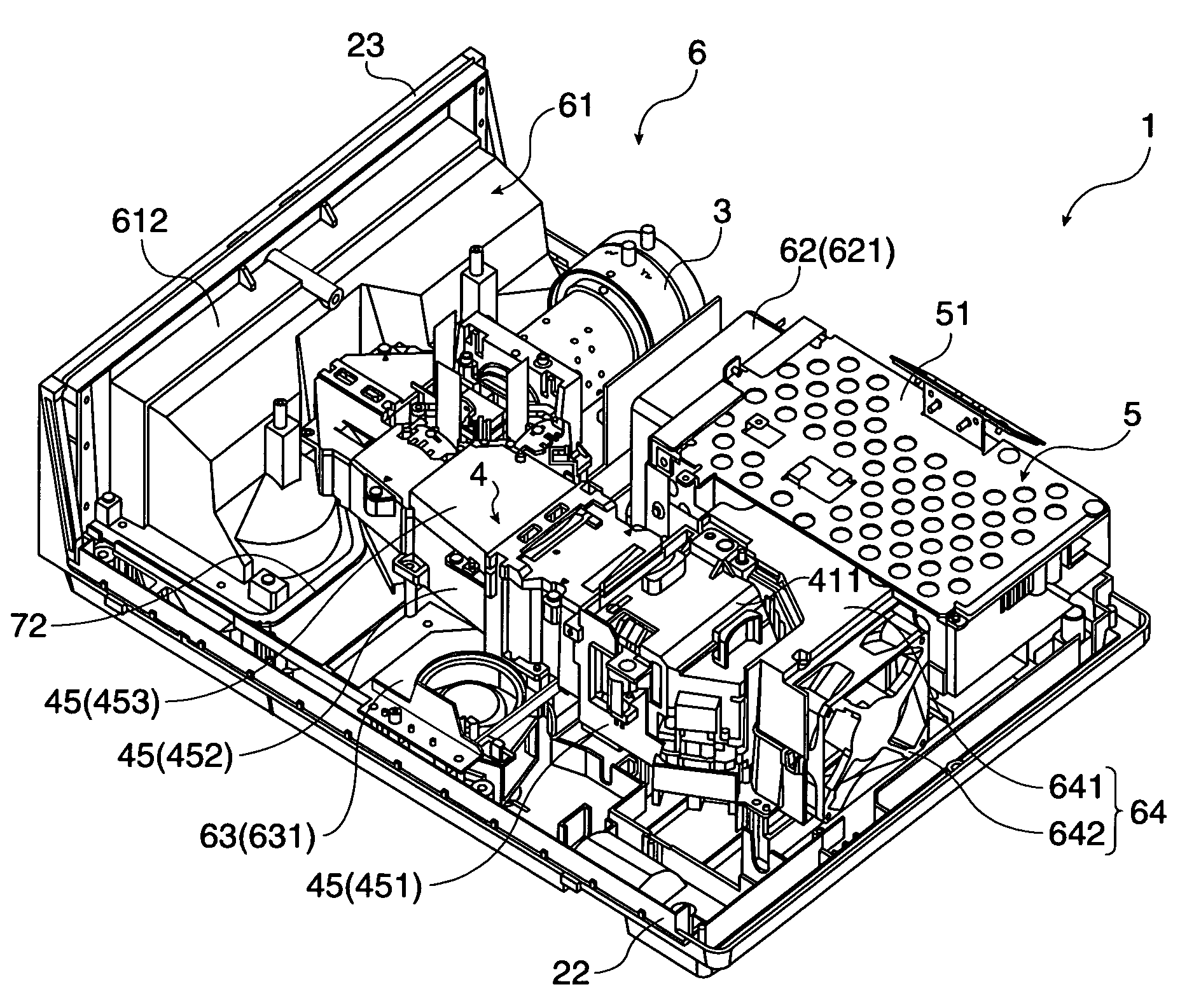
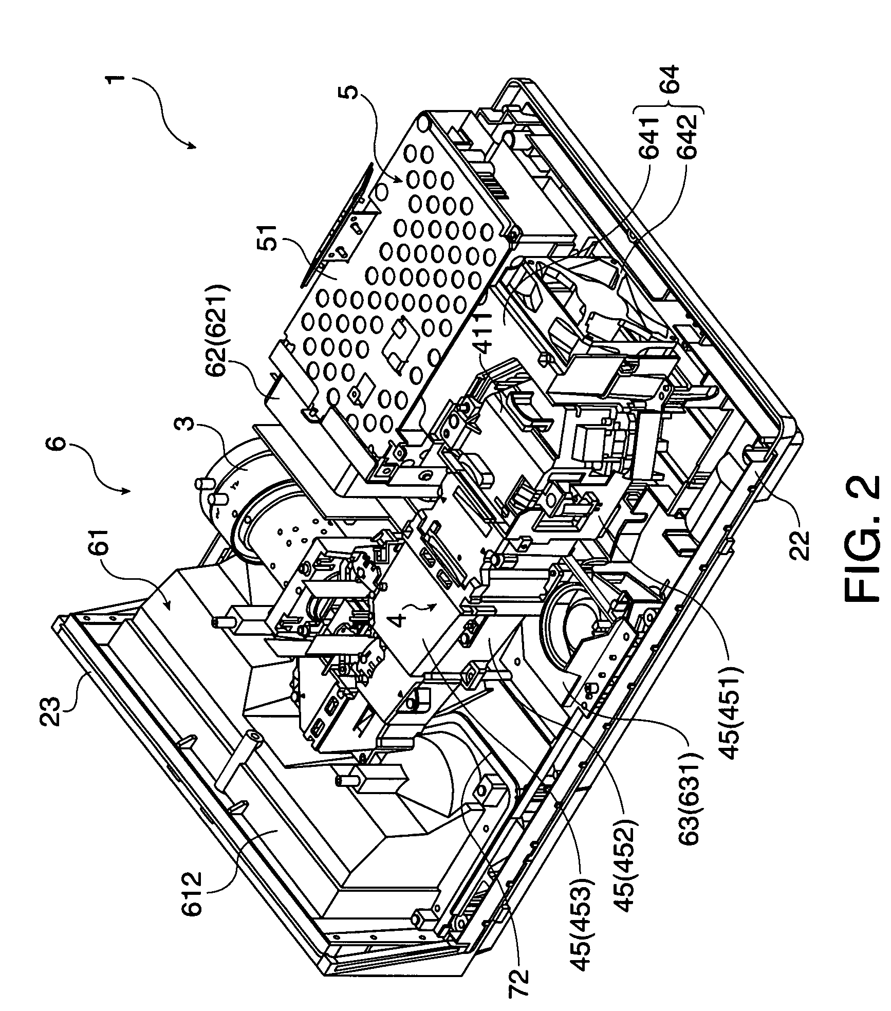
[0043]As shown in FIG. 1, the projector 1 includes an exterior casing 2 that is formed in a substantially cubic shape. The exterior casing 2 includes an upper case 21 that forms a top surface and sides of the projector 1, a lower case 22 that forms a bottom surface, and a side case 23 that forms sides in a projection direction of an optical image, which are fixed to one another by means of screws.

[004...


PUM


Abstract

A wind velocity measuring device is used in an electronic apparatus including cooled objects and cooling fans for cooling the cooled objects and measures a wind velocity of air blown to the cooled objects. The wind velocity measuring device includes a wind velocity measuring unit that measures a wind velocity of air, and an air circulating unit that circulates a portion of the air blown to the cooled objects. The air circulating unit includes barrier portions that extend to cross a circulation direction of the air at a front stage side of the circulation direction of the air, and an exhaust port that discharges inner air to the outside and is formed at a rear stage side of the circulating direction of the air, and the wind velocity measuring unit measures a wind velocity of the air between the barrier portions and the exhaust port in the air circulating unit.

Description

BACKGROUND[0001]1. Technical Field[0002]The present invention relates to a wind velocity measuring device and an electronic apparatus.[0003]2. Related Art[0004]Generally, various technologies have been known in which a wind velocity of air blown to cooled objects is measured and various controls are performed on the basis of the measured wind velocity, in an electronic apparatus that includes the cooled objects and cooling fans that cool the cooled objects (for example, JP-A-11-84534).[0005]In the technology that is disclosed in JP-A-11-84534, a suction fan blows a cooling air to a panel surface of a liquid crystal panel, and a wind velocity sensor measures a wind velocity of the cooling air that is blown to the panel surface of the liquid crystal panel. In addition, on the basis of the wind velocity measured by the wind velocity sensor, a protection device performs control for making a light source or a power supply turned off or control for making alarm display for an abnormal hea...

Claims


Application Information

Patent Timeline
Patent Type & Authority Patents(United States)
IPC IPC(8): H05K7/20G03B21/16
CPCG01P13/006H05K7/20172
Inventor SAEGUSA, TAKASHIARAI, TSUYOSHITAKASUKA, HIDEKIUCHIDA, MASAKISAKAI, YOHEI
Owner SEIKO EPSON CORP
Why Eureka
Try Eureka