Eureka AIR delivers breakthrough ideas for toughest innovation challenges, trusted by R&D personnel around the world.

Electric power-steering apparatus

a technology of electric steering and electric motor, which is applied in the direction of electrical steering, vehicle components, and gears, can solve the problems of torque transmission loss and shortened belt life, and achieve the effects of high reduction gear ratio, good mountability on vehicles, and easy adjustmen

Active Publication Date: 2009-05-26
JTEKT CORP +1
View PDF19 Cites 9 Cited by
  • Summary
  • Abstract
  • Description
  • Claims
  • Application Information

AI Technical Summary

Benefits of technology

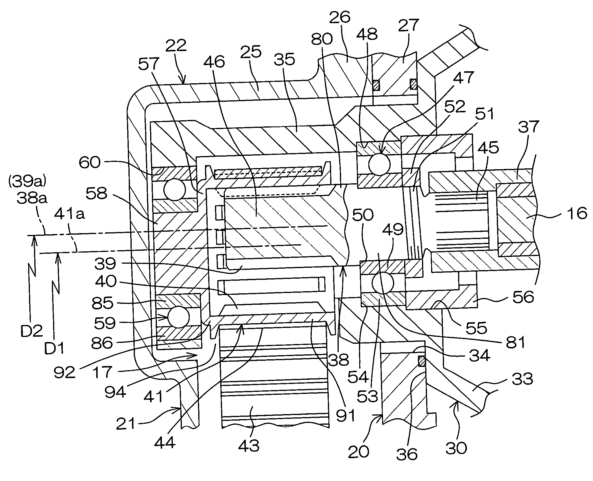
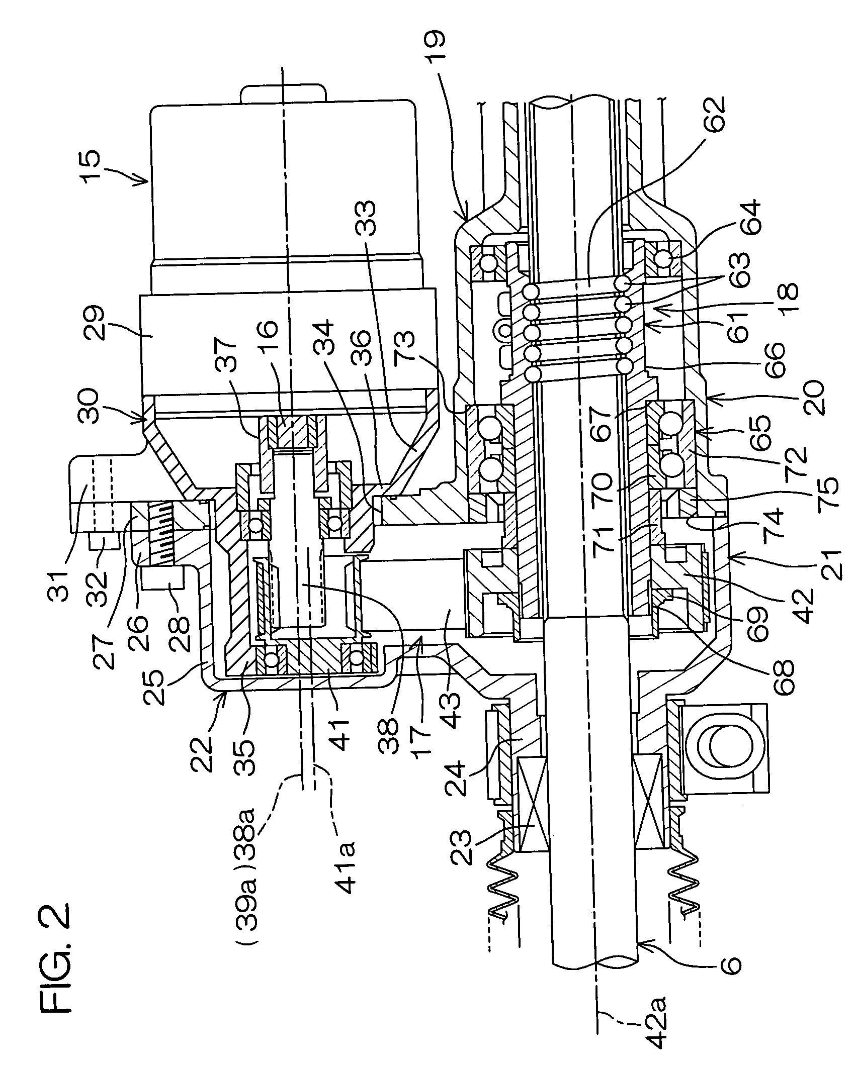
[0009]According to this embodiment, the rotation speed of the output shaft of the electric motor is reduced by the inscribed gear and the circumscribed gear, and thereafter it is reduced by the ratio between the diameters of the driving pulley and the driven pulley. Since the speed reduction using the inscribed gear and the circumscribed gear can heighten the reduction gear ratio, a high reduction gear ratio can be achieved with a small-sized reduction gear mechanism as a whole without a small-diameter driving pulley or a large-diameter driven pulley, thus to obtain a good mountability on a vehicle. Further, since it is not necessary to reduce the radius of curvature of the region of the driving pulley on which the belt is wound, the life of the belt can be extended.

Problems solved by technology

However, if the small pulley is made small-diameter for this purpose, the radius of curvature of a belt region wound on the small pulley becomes small and it is feared that the life of belt is shortened because of its flexion fatigue.
Besides, it is feared that torque transmission loss is caused by increased inner friction at curved portions of the belt.

Method used


Image

  • Electric power-steering apparatus
  • Electric power-steering apparatus
  • Electric power-steering apparatus

Examples


Embodiment Construction

[0016]Preferred embodiments of the present invention will be described below with reference to the appended drawings.

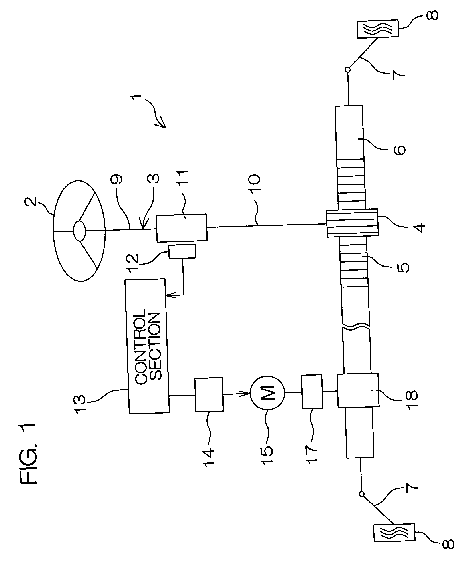
[0017]FIG. 1 is a pattern diagram of the schematic structure of an electric power steering apparatus according to an embodiment of the present invention. Referring to FIG. 1, the electric power steering apparatus (EPS) 1 comprises a steering shaft 3 connected to a steering wheel 2 as a steering member at an end of the steering shaft 3, a pinion 4 provided at the other end of the steering shaft 3, and a rack shaft 6 as a steerable shaft having rack teeth 5 engageable with the pinion 4 and extending in the direction of the width (transverse direction) of a vehicle.

[0018]Connected respectively to both ends of the rack shaft 6 are tie rods 7, each of which is connected through a corresponding knuckle arm (not shown) to a corresponding wheel 8. When the steering wheel 2 is operated to rotate the steering shaft 3, this rotation of the steering shaft 3 is converted through t...


PUM


Abstract

An electric power steering apparatus includes a reduction gear mechanism (17) for reducing the rotation speed of an output shaft (16) of an electric motor (15). The reduction gear mechanism (17) comprises an inscribed gear (39) rotatable interlockingly with the output shaft (16), and a circumscribed gear (40) in which the inscribed gear (39) is inscribed. An endless belt connects a driving pulley (41) integrally rotatable with the circumscribed gear (40) and a driven pulley (42) disposed so as to surround a steerable shaft. By heightening the reduction gear ratio by the speed reduction using the inscribed gear (39) and the circumscribed gear (40), the reduction gear mechanism (17) as a whole can achieve a high reduction gear ratio without making the diameter of the driving pulley (41) very small.

Description

TECHNICAL FIELD[0001]The present invention relates to an electric power steering apparatus in which steering assist force is generated by an electric motor.BACKGROUND ART[0002]In a rack assist type electric power steering apparatus, the rotation of an electric motor is slowed down by a reduction gear mechanism comprising a pulley-belt mechanism and thereafter converted into the axial movement of a rack shaft, for example, through a ball screw mechanism surrounding the rack shaft (see, for example, Japanese Examined Patent Publication No. 4(1992)-28583).[0003]The abovementioned pulley-belt mechanism comprises a small pulley disposed on the same axis line with an output shaft of the electric motor, and a large pulley surrounding the rack shaft.[0004]A reduction gear mechanism of such a kind of electric power steering apparatus is required to be small-sized and at the same time to obtain a high reduction gear ratio.[0005]However, if the small pulley is made small-diameter for this purp...

Claims


Application Information

Patent Timeline
Patent Type & Authority Patents(United States)
IPC IPC(8): B62D5/04F16H7/02F16H37/02
CPCB62D5/0424F16H37/02F16H7/023F16H2025/2096
Inventor MURAKAMI, TETSUYAMIYATA, ATSUYAMURATAKA, HIROSHIHIRONAKA, AKIHIRO
Owner JTEKT CORP
Why Eureka
Eureka Blog
Learn More