Method and device for discharging and dehumidifying air in a cooking area

a technology for discharging and dehumidifying air and cooking area, which is applied in the direction of separation process, chemical/physical process, domestic stoves or ranges, etc., can solve the problems of difficult installation, difficult installation, and often problematical installation and complex installation, so as to improve water separation and improve efficiency

Inactive Publication Date: 2009-05-26
BSH BOSCH & SIEMENS HAUSGERAETE GMBH
View PDF12 Cites 4 Cited by
  • Summary
  • Abstract
  • Description
  • Claims
  • Application Information

AI Technical Summary

Benefits of technology

[0014]The object of the present invention is to create a method for discharging vapor-laden air in cooking areas and a corresponding device having improved water separation as well as an improved efficiency.

Problems solved by technology

Numerous problems that occur in conjunction with treatment of air are known from the state of the art.
However, this is not to exclude other application fields with which those skilled in the art may be familiar, i.e., fields where the situation is similar or special cutting manufacturing machines in factories that are cooled with an oil-in-water emulsion.
In general the problem of having to remove the vapors and / or odors formed in cooking occurs in cooking areas.
The effect of such exhaust hoods is good in principle, but installation is often problematical and very complex.
Installation is not even possible in many homes, because there is no outside air connection, for example, or it cannot be implemented at a reasonable expense.
In the long run, however, such vent hoods may also constrict or even block an exhaust duct such as a chimney due to cooking deposits or may even destroy them due to a buildup of soot.
The effect of such known circulating hoods is unsatisfactory, however, mainly for the following reasons.
Furthermore, elimination of odors by the activated carbon filter is satisfactory for only a short period of time because the activated carbon filter rapidly becomes clogged mainly by fine particles of fat and water molecules not retained by the fat filter.
The activated carbon filter therefore becomes ineffective and must be replaced frequently.
However, the good effect described in DE 299 03 794 U1 is limited essentially to filtering out relatively large fluid and solid particles, but also it produces a loud flowing noise.
Functioning is possible only in the so-called “fog range.” However it is impossible to separate moisture from a mixture of air and water vapor using this device.
With this device, in general the dew point of humid air cannot be reached in general.
The water separation effect is inadequate.
Furthermore, this approach results in high flowing noises on the one hand while on the other hand also resulting in a very complex internal structure involving problems in production and cleaning.
Therefore, this approach has the disadvantage of having a high electric power demand during operation of such a vapor vent hood in addition to its large size.

Method used


Image

  • Method and device for discharging and dehumidifying air in a cooking area
  • Method and device for discharging and dehumidifying air in a cooking area
  • Method and device for discharging and dehumidifying air in a cooking area

Examples


Embodiment Construction

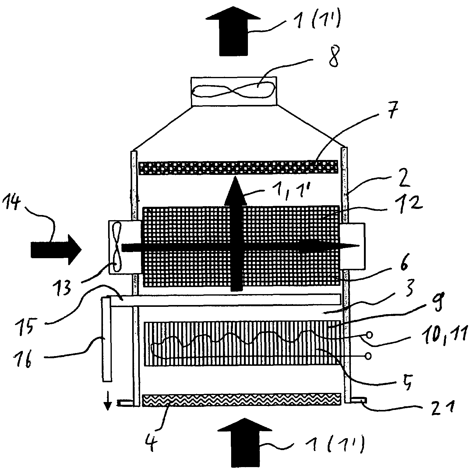
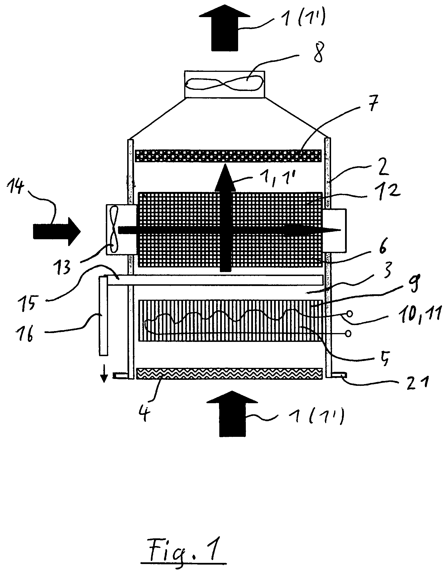
[0041]FIG. 1 shows a vapor-discharging device which is preferably arranged above a cooking area (not shown) to remove an airstream 1 laden with cooking vapors and fumes. The vapor-discharging device has a housing 2 which has a main line 3 for the airstream 1. The vapor-discharging device according to FIG. 1 first has a fat filter 4 in the direction of flow of the airstream 1, then a sorbent 5, next a condensation unit 6, following that an odor filter 7 and then a fan 8. A screen or a hood 21 may also be provided to better guide the cooking vapors to the vapor-discharging device.

[0042]The fat filter 4 is preferably designed as an expanded metal filter or as an eddy current filter or as a labyrinth filter or even as a nonwoven filter. The fat filter 4 serves to remove fat, oil and water droplets present in the airstream out of the airstream 1.

[0043]In the present exemplary embodiment, CaCl2 or LiCl or silica gel or a zeolite is used as the sorbent for adsorbing or absorbing water. The...


PUM

PropertyMeasurementUnit
period of timeaaaaaaaaaa
flow rateaaaaaaaaaa
temperatureaaaaaaaaaa

Abstract

A method and a device for discharging air current from a cooking area. The method and the device guide the air current through a sorption agent for absorbing water or water vapor contained in the air current. The sorption agent is regenerated preferably when the air current is not being discharged from the cooking area.

Description

CROSS-REFERENCE TO RELATED APPLICATIONS[0001]Not ApplicableSTATEMENT REGARDING FEDERALLY SPONSORED RESEARCH OR DEVELOPMENT[0002]Not ApplicableTHE NAMES OF THE PARTIES TO A JOINT RESEARCH AGREEMENT[0003]Not ApplicableINCORPORATION-BY-REFERENCE OF MATERIAL SUBMITTED ON A COMPACT DISC[0004]Not ApplicableBACKGROUND OF THE INVENTION[0005]1. Field of the Invention[0006]The present invention relates to a method for discharging vapor-laden air in a cooking area and a corresponding vapor-discharging device. In addition, this invention relates to a method for operating a vent device.[0007]2. Description of Related Art[0008]Numerous problems that occur in conjunction with treatment of air are known from the state of the art. For the user, such problems are noticeable most clearly and most directly in discharging cooking vapors and / or other kitchen odors, especially in a cooking area, so that this group of problems is of primary concern within the scope of the present invention. However, this i...

Claims


Application Information

Patent Timeline
Patent Type & Authority Patents(United States)
IPC IPC(8): B01D53/26F24C15/20B01J20/34F24F3/14
CPCB01D53/261B01J20/046B01J20/103B01J20/18B01J20/20F24C15/2035B01J20/3408B01J20/3433B01J20/3441B01J20/3483B01J20/2805F24F3/1411Y10S55/36
Inventor DAMRATH, JOACHIMHAUER, ANDREASKORNBERGER, MARTINLAEVEMANN, EBERHARD
Owner BSH BOSCH & SIEMENS HAUSGERAETE GMBH
Why Eureka
Try Eureka