Method for reducing delay difference of differential transmission and system thereof

a differential transmission and delay difference technology, applied in pulse manipulation, pulse technique, instruments, etc., can solve the problems of deteriorating system performance, increasing the error of the optimum sampling point for clock and data recovery (cdr), and increasing the bit error ratio (ber) of received data, so as to reduce reduce the delay inconsistency between pins of the connector. , the effect of reducing the delay difference of differential transmission

Inactive Publication Date: 2009-05-26
HUAWEI TECH CO LTD
View PDF3 Cites 6 Cited by
  • Summary
  • Abstract
  • Description
  • Claims
  • Application Information

AI Technical Summary

Benefits of technology

[0013]As seen from the above mentioned schemes, the system and method for reducing delay difference of differential transmission provided in the present invention is to generate a certain delay difference between waveform of P signal and that of N signal through measuring the delay difference of differential transmission and performing delay adjustment to P signal or N signal of the differential signals based on the measured delay difference, to compensate for the delay difference of differential transmission generated in the channels. Therefore, the delay difference of differential transmission caused by property discrepancy of board materials and delay inconsistency among pins of the connectors can be reduced, and at same time the scheme design is simplified.

Problems solved by technology

However, due to certain reasons such as anisotropy of the printed circuit board materials and discrepancy in real distance of differential cable, the transmission delay of the two signals with opposite polarities are inconsistent during the differential signal transmission, which means that the delay difference of the differential transmission is not zero.
Therefore, the bigger the delay difference of differential transmission is, the heavier the signal jitters will occur at the receiving end, and the larger the error of the optimum sampling points for Clock and Data Recovery (CDR) will become.
Deterioration of the optimum sampling points may further increase the Bit Error Ratio (BER) of received signal at the receiving end, and deteriorate the system performance.
As to the signal with relatively high speed, any deterioration may result in a sharp increase of BER, even to the extent of abnormal operation of system.

Method used


Image

  • Method for reducing delay difference of differential transmission and system thereof
  • Method for reducing delay difference of differential transmission and system thereof
  • Method for reducing delay difference of differential transmission and system thereof

Examples


Embodiment Construction

[0025]The present invention is hereinafter described in detail with reference to the accompanying drawings and the embodiments.

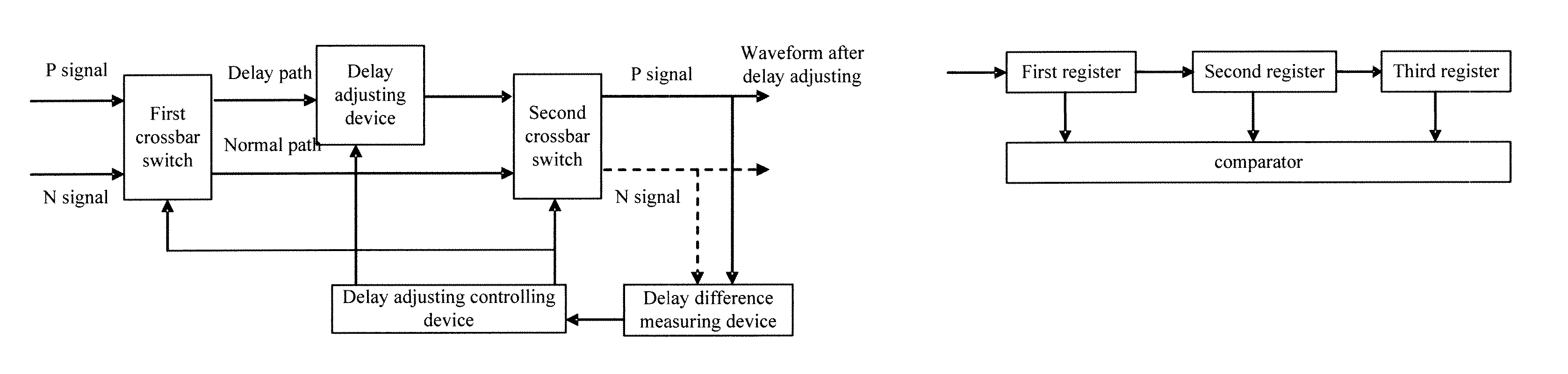
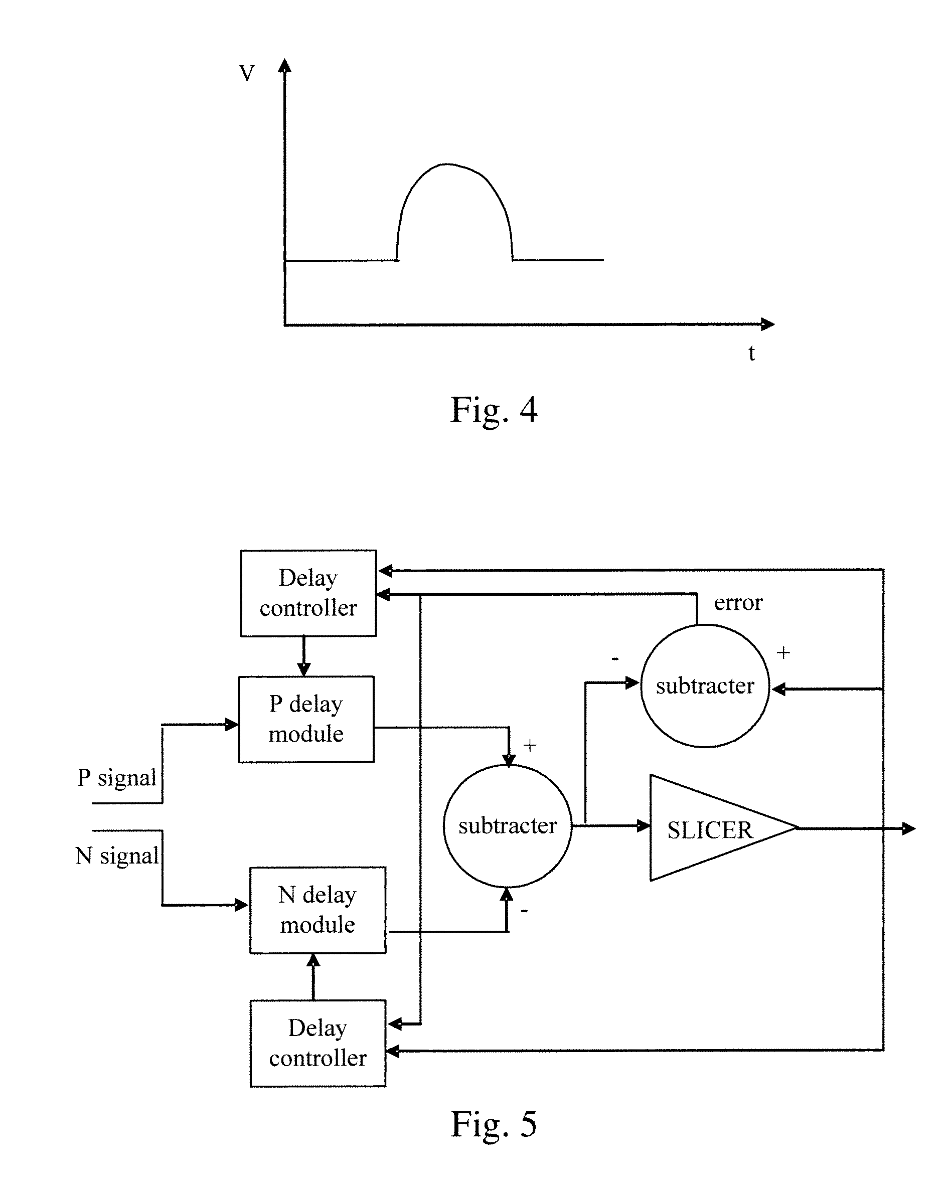
[0026]According to an embodiment of the present invention, the delay difference between P signal and N signal of the differential signals at the receiving end is measured, and then the P signal or N signal of the differential signals at the transmitting end is adjusted based on the delay difference. The delay difference of differential transmission is eliminated or reduced through measurement, feedback and adjusting.

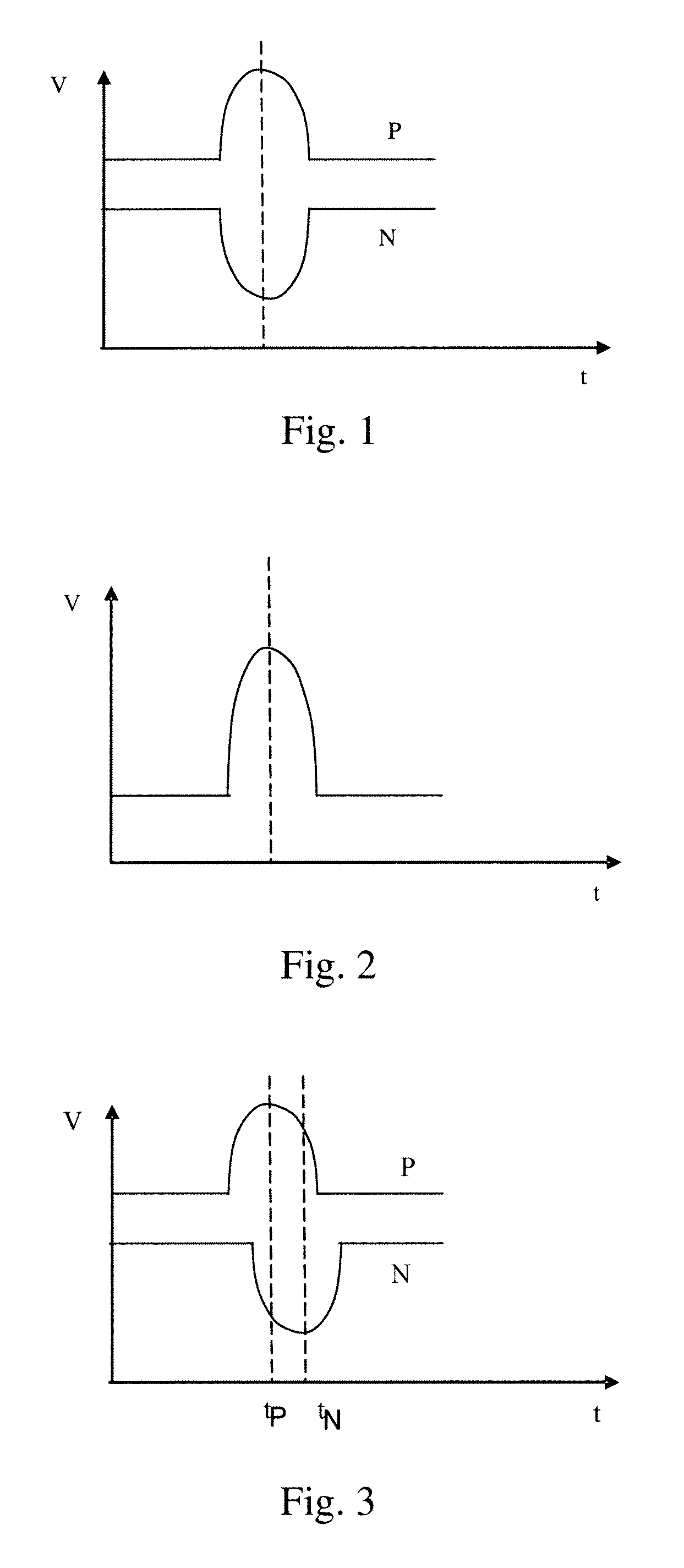
[0027]The delay difference measured at the receiving end may be voltage difference or time difference.

[0028]The invention will be described in more detail hereinafter with reference to the embodiments by taking the measured voltage difference as an example.

[0029]The system for reducing delay difference of differential transmission according to the embodiment of the present invention includes, as shown in FIG. 6, a delay adjustment device, a delay...


PUM


Abstract

The present invention discloses a system and method for reducing delay difference of differential transmission, a certain delay difference between waveforms of the P signal and N signal is generated through controlling delay adjustment to P signal or N signal of the differential signals and controlling delay adjustment value simultaneously, to compensate for the delay difference of differential transmission due to the channels. Therefore, the present invention can reduce the delay difference of differential transmission due to property discrepancy of board materials and delay inconsistency among pins of the connectors, and at same time simplify the scheme design.

Description

CROSS-REFERENCE TO RELATED APPLICATION[0001]This application claims the benefit of Chinese Patent Application No. 200510102696.X, which was filed on Sep. 13, 2005, the entire disclosure of which is hereby incorporated herein by reference.BACKGROUND OF THE DISCLOSURE[0002]1. Field of the Technology[0003]The present invention relates to signal transmission technology, and more particularly, to a method and system for reducing delay difference of differential transmission.[0004]2. Background of the Invention[0005]Along with the rapid development of high speed interconnection technology, the speed of channel transmission has become increasingly higher and has reached 10 Gbps. Generally, a pair of differential signals is adopted for high speed signal transmission. The pair of differential signals includes two signals with opposite polarities, one of which is defined as positive signal, i.e., P signal while the other is defined as negative signal, i.e., N signal. Therefore, the differenti...

Claims


Application Information

Patent Timeline
Patent Type & Authority Patents(United States)
IPC IPC(8): H03H11/26H03H11/16
CPCH04L49/40H04L49/101
Inventor JIA, GONGXIANWANG, LUNHUANG, CHUNXING
Owner HUAWEI TECH CO LTD
Why Eureka
Try Eureka