Configurable multi-mode modulation system and transmitter

a multi-mode modulation and transmitter technology, applied in the direction of low-noise amplifiers, amplifier types, amplifiers, etc., can solve the problems of undesirable am to am and am to pm distortion, linear pas are very inefficient, and existing gsm modulation schemes and chip set architectures are not easily adapted to transmit signals

Active Publication Date: 2009-05-26
OGM LAB +1
View PDF15 Cites 57 Cited by
  • Summary
  • Abstract
  • Description
  • Claims
  • Application Information

AI Technical Summary

Problems solved by technology

Unfortunately, existing GSM modulation schemes and chip set architectures are not easily adapted to transmit a signal that includes both a PM component and an AM component.
Unless the PA is very linear, it may distort the combined transmission signal by causing undesirable AM to AM and AM to PM distortion.
Linear PAs are very inefficient, however, thus consuming significantly more power than a non-linear PA and drastically reducing the life of the battery or other power source.
However, the power consumption benefits of using a non-linear, highly efficient PA when employing a GMSK system are not realized in the EDGE system using a highly linear PA.
Further, manufacturers desire to quickly modify transmitter architectures as market and standards-based changes influence what is a preferred implementation, but this can be difficult when different architectures are designed with different components.
There are cost, size, performance, and manufacturability tradeoffs associated with linear and dual mode PAs.

Method used


Image

  • Configurable multi-mode modulation system and transmitter
  • Configurable multi-mode modulation system and transmitter
  • Configurable multi-mode modulation system and transmitter

Examples


Embodiment Construction

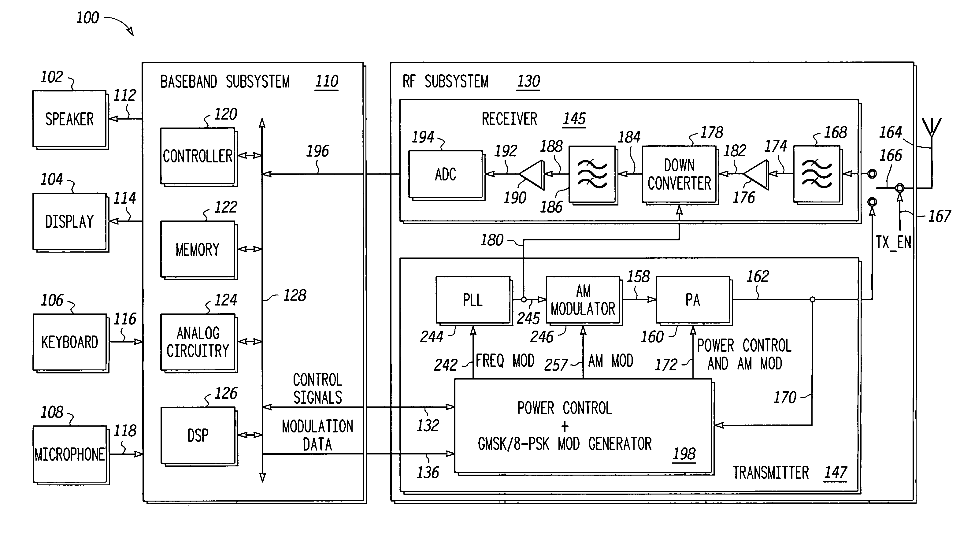
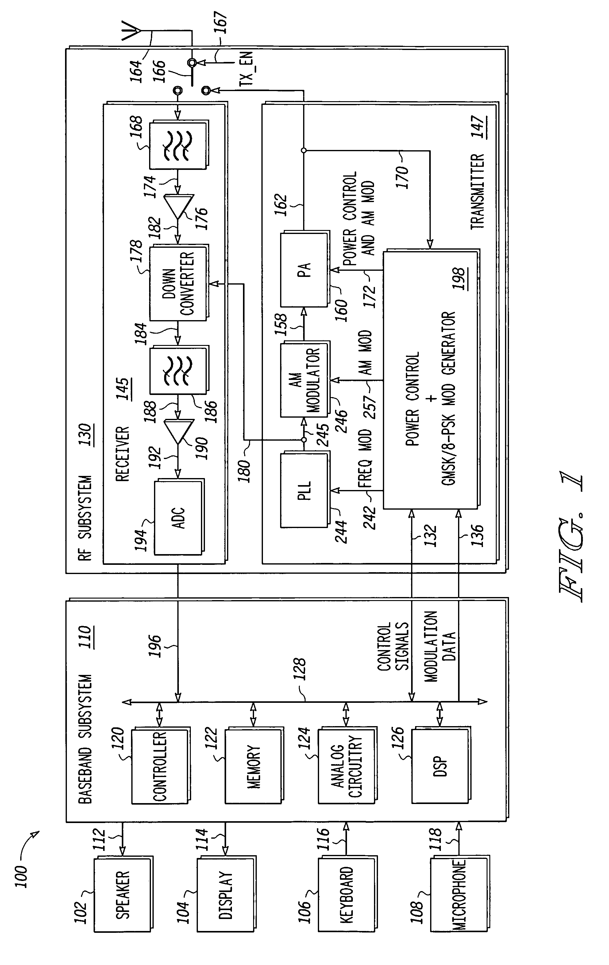
[0019]With reference now to the figures, and in particular with reference to FIG. 1, there is shown a simplified block diagram illustrating a portable radio communications device 100, in accordance with a preferred embodiment of the invention. Communications device 100 includes speaker 102, display 104, keyboard 106, and microphone 108, all connected to baseband subsystem 110. In a particular embodiment, communications device 100 can be, for example but not limited to, a portable telecommunication handset such as a mobile cellular-type telephone. Speaker 102 and display 104 receive signals from baseband subsystem 110 via connections 112 and 114, respectively, as known to those skilled in the art. Similarly, keyboard 106 and microphone 108 supply signals to baseband subsystem 110 via connections 116 and 118, respectively, as known to those skilled in the art. Baseband subsystem 110 includes controller 120, memory 122, analog circuitry 124, and digital signal processor (DSP) 126 in co...


PUM


Abstract

A multi-mode transmitter architecture is configurable for multiple modulation modes using either polar or polar-lite modulation. Multiplexed signal paths and reconfigurable components are controlled for performance in GMSK and EDGE burst modes. Polar-lite EDGE modulation is programmed by setting a multiplexer coupling a first amplitude modulated signal path with a frequency modulated signal path input to a dual-mode power amplifier for amplification of the combined EDGE transmission signal. In full-polar EDGE modulation, amplitude modulated signal is multiplexed into a second amplitude modulated signal path for A / D conversion and comparison with a polar feedback signal coupled from the power amplifier output. The resulting comparison is applied to a power control port of the power amplifier to amplitude modulate the EDGE transmission output. Multiplexers are configured to disconnect the amplitude modulated paths when operating in GMSK signaling for both full-polar and polar-lite modulation. Multiplexers selectively couple power feedback into the second amplitude modulated signal path to provide power control and output power ramping for burst transmissions.

Description

BACKGROUND OF THE INVENTION[0001]1. Field of the Invention[0002]The present invention relates generally to modulation and power control in a wireless communication device transmitter, and more particularly to a system for implementing amplitude and phase modulation with a closed or open power control feedback loop capable of supporting either a linear or a non-linear saturated mode power amplifier.[0003]2. Description of the Related Art[0004]With the increasing availability of efficient, low cost electronic modules, mobile communication systems are becoming more and more widespread. For example, there are many variations of communication schemes in which various frequencies, transmission schemes, modulation techniques and communication protocols are used to provide two-way voice and data communications in a handheld telephone like a communication handset. These variations include, for example, global system for mobile communication (GSM) radios, code division multiple access (CDMA) ...

Claims


Application Information

Patent Timeline
Patent Type & Authority Patents(United States)
IPC IPC(8): H04B1/02
CPCH03F1/0205H03F3/24H04B1/0483H04B1/406H03F2200/294H03F2200/372H04B2001/0433H03F1/34
Inventor PECKHAM, DAVID S.MEADOR, RICHARD B.TRAYLOR, KEVIN B.
Owner OGM LAB
Why Eureka
Try Eureka