
Synchronized multichannel universal serial bus

a multi-channel, universal serial bus technology, applied in multiplex communication, generating/distributing signals, instruments, etc., can solve the problems of severe restrictions, insufficient specification, and the inability to meet the needs of users, and achieve the effect of not placing a great computational burden on the hos

Inactive Publication Date: 2009-05-26
CHRONOLOGIC PTY LTD
View PDF23 Cites 28 Cited by
  • Summary
  • Abstract
  • Description
  • Claims
  • Application Information

AI Technical Summary

Benefits of technology

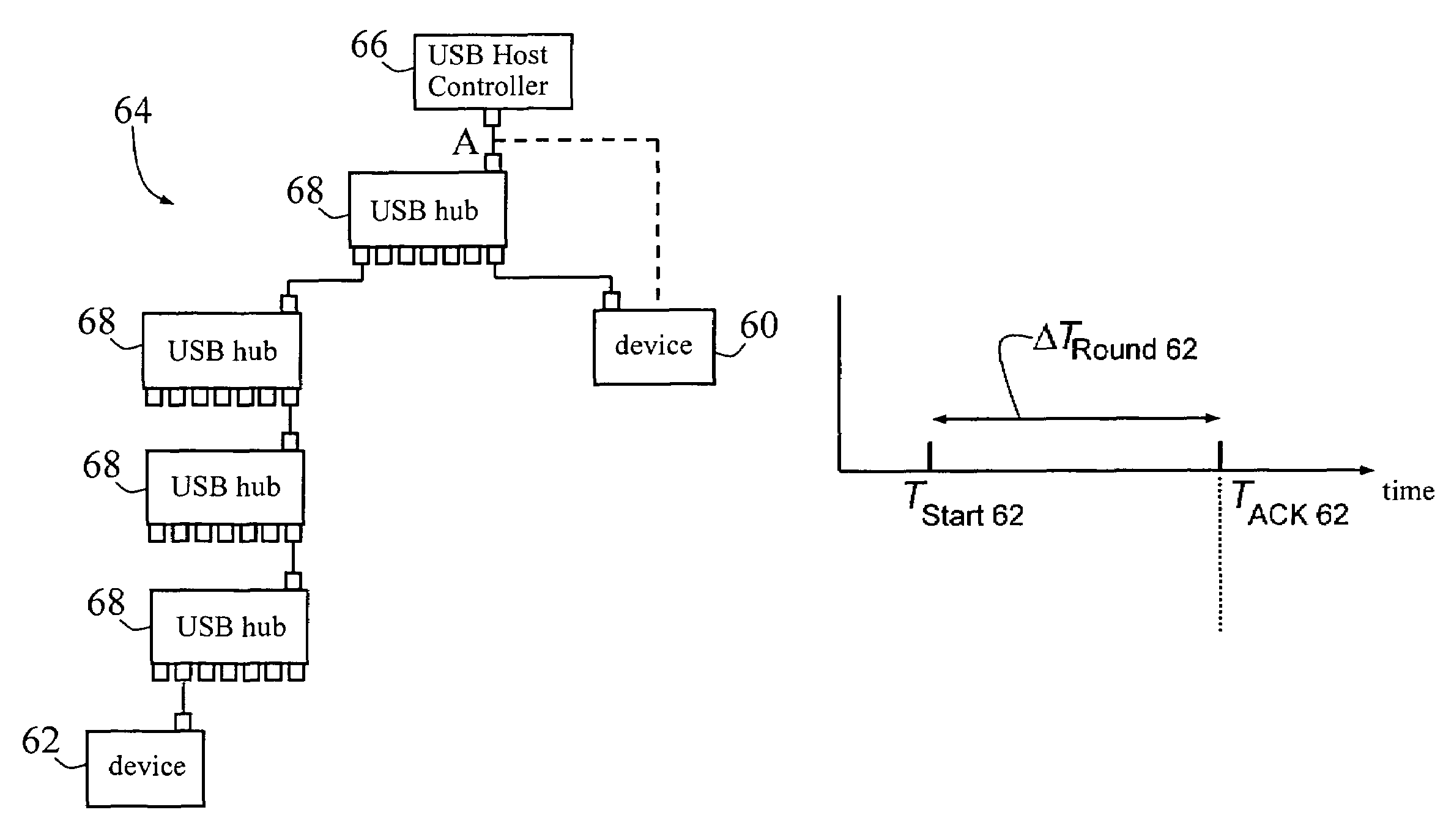
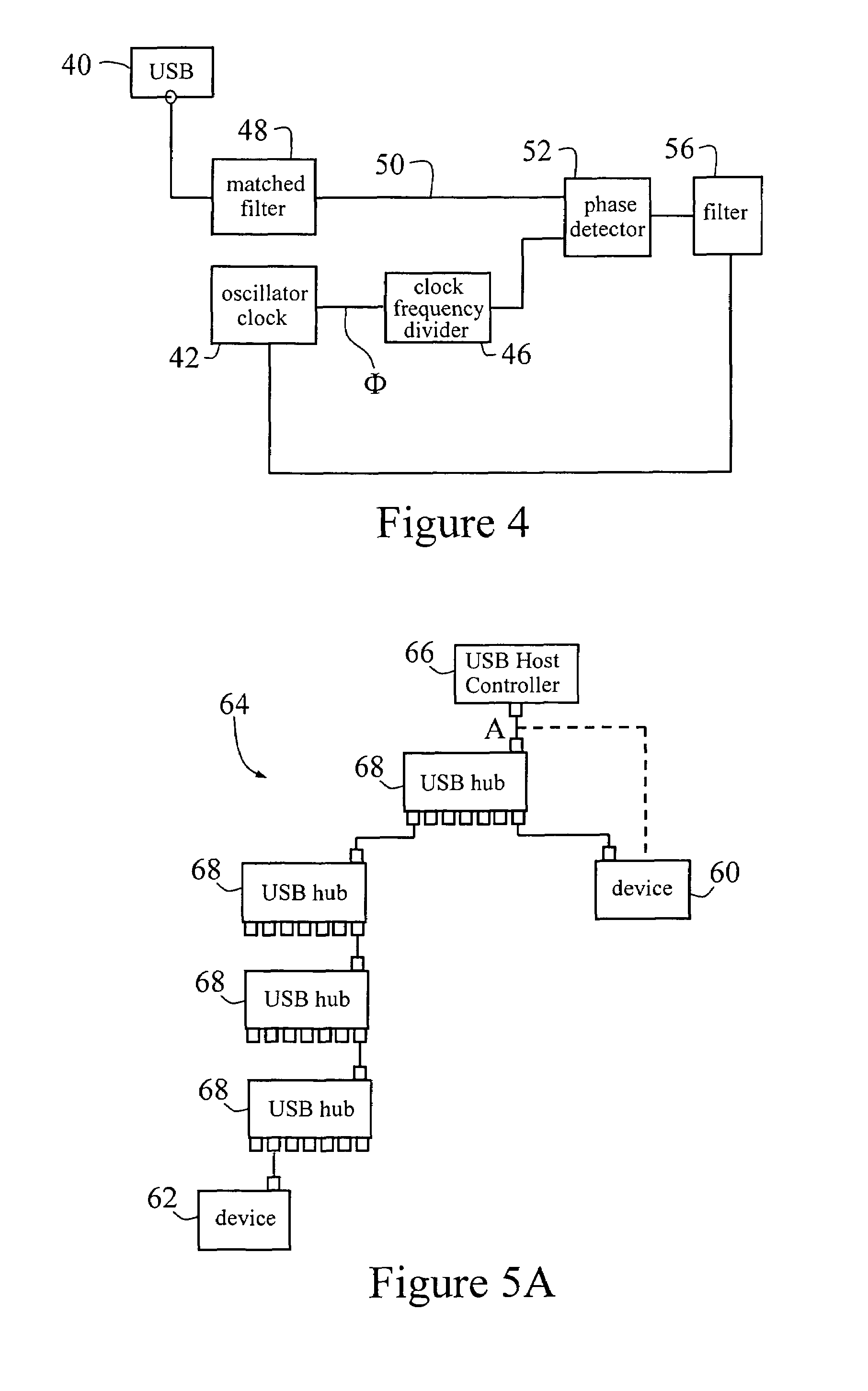
"The present invention provides a method and apparatus for synchronizing USB devices connected to a USB host with each other. The invention allows for any number of USB devices to operate in a synchronized and triggered manner without placing a great computational burden on the host. The invention provides a synchronized multichannel universal serial bus that can observe USB traffic, lock a local clock signal of a USB device to a periodic signal contained in USB data traffic, and measure the round trip time of individual packets to determine relative phases of individual USB devices. The invention also includes circuitry to issue all devices in a USB topology with a trigger signal and to provide synchronization signals to USB devices at frequencies that correspond to national standards. The invention provides a method for locking the local clock of each of a plurality of USB devices within the same USB tree to substantially the same frequency."

Problems solved by technology

The specification does not sufficiently address this issue.
This is a severe restriction when there is a need to synchronize devices at MHz levels and above.
This unfortunately means that the available USB bandwidth can be used up before the maximum number of devices has been connected.
This approach also places on the host the great computational burden of keeping 127 devices synchronized to the host by means of software, yet still fails to address maintaining synchrony between the devices as to the host the individual devices represent separate processes.
However, the specification does not address the potential problems of synchronizing 100 USB-speaker pairs.
Further, neither a frequency lock to 1 kHz or better stability nor high accurate phase control is disclosed.
This document, however, relates to the synchronization of two USB hosts with each other (and with limited accuracy), not to the synchronization of a multiplicity of USB devices to a single USB host.
Although the above is not intended to be exhaustive or to describe the common general knowledge in this area, it is clear that there are deficiencies in the current art.

Method used


Image

  • Synchronized multichannel universal serial bus
  • Synchronized multichannel universal serial bus
  • Synchronized multichannel universal serial bus

Examples


example 1

With No Additional Connector Wiring for Synchronization

[0165]The advantage of a system according to the present invention that does not depend on supplementary synchronization signals is that the devices are not reliant on this information to work in a synchronized manner, and hence ordinary hubs can be used on any standalone host. Such a system can be extended to devices that require very accurate synchronization. Thus, an example of such a system is shown in FIG. 7 generally at 96, with upstream USB port 98 and a plurality of back plane hub devices 100, 102 (each, in this example, a 7-port USB hub on back plane 104), which may optionally supply additional power to a plurality of devices 106. Each device 106 may contain a local clock that is frequency and phase locked according to the above-described second embodiment. The back plane 104 and the hubs 100, 102 have the ability to time phase differences between devices 106 (each with random cable length according to the USB specifica...

example 2

[0166]A complex system comprising many synchronous USB devices is shown in FIG. 8 generally at 110. Upstream port 111 receives USB communication from the Host. The system 110 includes a plurality of back planes 112, 113, 114 each provided with two back plane hub devices 115. Each back plane hub devices 115 comprises a 7-port USB hub and may optionally supply additional power to a plurality of devices 116. Each device 116 may contain a local clock which is frequency and phase locked according to the above-described second embodiment. Further, first or master back plane 112 also has additional circuitry or logic elements 117 (as in FIG. 7), and has the ability to time phase differences between devices 116 (each with different connection topology) by means of elements 117 and the techniques described above in the context of the third embodiment. Furthermore each device 116 contains a phase shift generator for phase shifting the local clock using the techniques described above in the th...

example 3

Additional Connector Wiring for Synchronization

[0168]The simplest example of such an approach according to the above-described embodiments is achieved by connecting all devices to a common synchronization signal either through a proprietary connector containing USB and synchronization information or through a USB connector, as well as a separate synchronization link. The synchronization information is independent of the USB traffic and can therefore be of arbitrary frequency without any great difficulty. The medium for the synchronization information can be any of wireless, electrical or fiber optic means. FIG. 9 depicts schematically a practical example of such a circuit at 120. The circuit 120 includes, in effect, a pair of circuits each comparable to that of FIG. 7, so that 24 USB devices 122 are connected via 7-port USB hubs 124; these in turn can be connected to a PC via upstream USB ports 126. The USB connection topology has no influence on the synchronization signal, which is...


PUM


Abstract

The invention provides a method and apparatus for providing a synchronized multichannel universal serial bus, the method in one aspect comprising supplementing the signal channels in the USB specification to provide synchronization information from an external source, and in another aspect comprising observing USB traffic and locking a local clock signal of a USB device to a periodic signal contained in USB data traffic, wherein the locking is in respect of phase and / or frequency.

Description

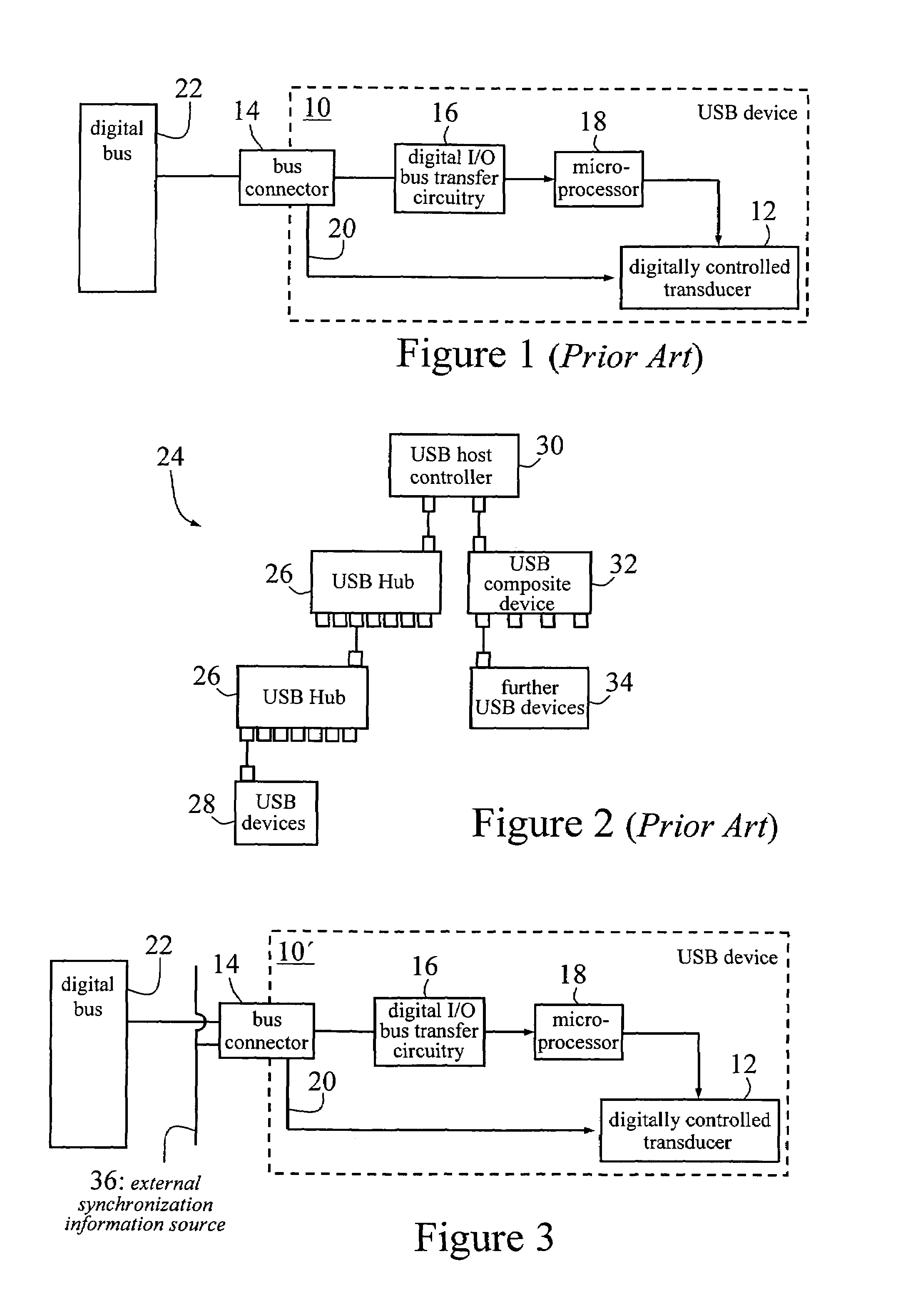
[0001]This application claims benefit of U.S. Provisional Application No. 60 / 396,099, filed Jul. 17, 2002.FIELD OF THE INVENTION[0002]The present invention relates to a method and apparatus for synchronizing Universal Serial Bus (USB) devices, of particular but by no means exclusive application in synchronizing USB devices connected to a USB host with respect to each other and to an arbitrary precise degree.BACKGROUND OF THE INVENTION[0003]The USB specification is intended to facilitate the interoperation of devices from different vendors in an open architecture. USB data is encoded using differential signalling (viz. two wires transfer the information) in the form of the difference between the signal levels of those two wires. The USB specification is intended as an enhancement to the PC architecture, spanning portable, desktop and home environments.[0004]By way of example, FIG. 1 is a schematic diagram of an illustrative prior art USB device 10 including a digitally controlled tra...

Claims


Application Information

Patent Timeline
Patent Type & Authority Patents(United States)
IPC IPC(8): G06F13/42G06F1/04G06F1/12H04L7/00G06F13/00G06F3/00H04J3/06
CPCG06F13/426G06F13/4278H04L7/0008H04J3/0682
Inventor FOSTER, PETER GRAHAMGOLDSMITH, CLIVE ALEXANDERKLOVEKORN, PATRICKWEIGOLD, ADAM MARK
Owner CHRONOLOGIC PTY LTD
Features
  • Generate Ideas
  • Intellectual Property
  • Life Sciences
  • Materials
  • Tech Scout
  • Unparalleled Data Quality
  • Higher Quality Content
  • 60% Fewer Hallucinations
Learn More