Synchronized multichannel universal serial bus

Inactive Publication Date: 2006-03-23
CHRONOLOGIC PTY LTD
16 Cites 47 Cited by

AI-Extracted Technical Summary

Problems solved by technology

The specification does not sufficiently address this issue.
This is a severe restriction when there is a need to synchronize devices at MHz levels and above.
This unfortunately means that the available USB bandwidth can be used up before the maximum number of devices has been connected.
This approach also places on the host the great computational burden of keeping 127 devices synchronized to the host by means of software, yet still fails to address maintaining synchrony between the devices as to the host the individual devices represent separate processes.
However, t...

Method used

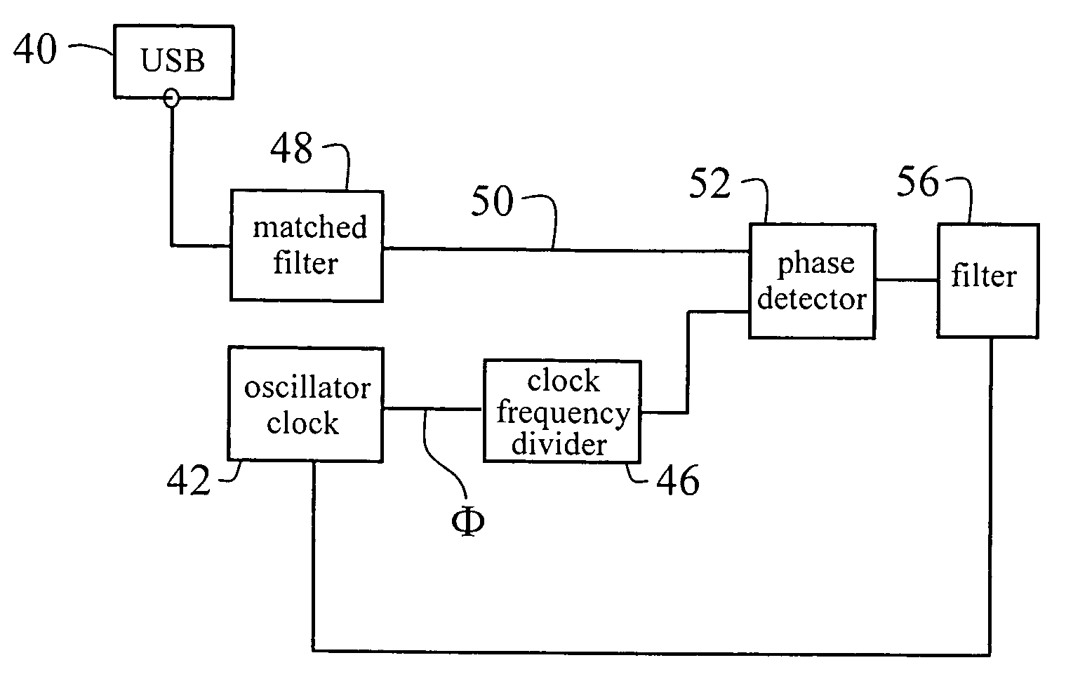
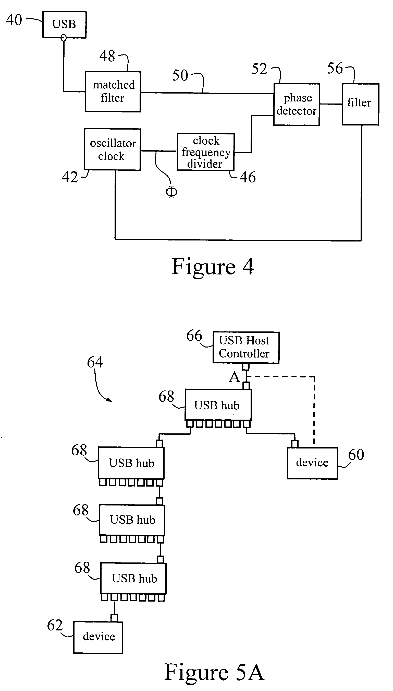
[0158] To eliminate the problems of jitter the SOF signal is latched to the local oscillator. The latch registers the arrival of an SOF trigger request, but only produces a trigger signal when the local o...

Benefits of technology

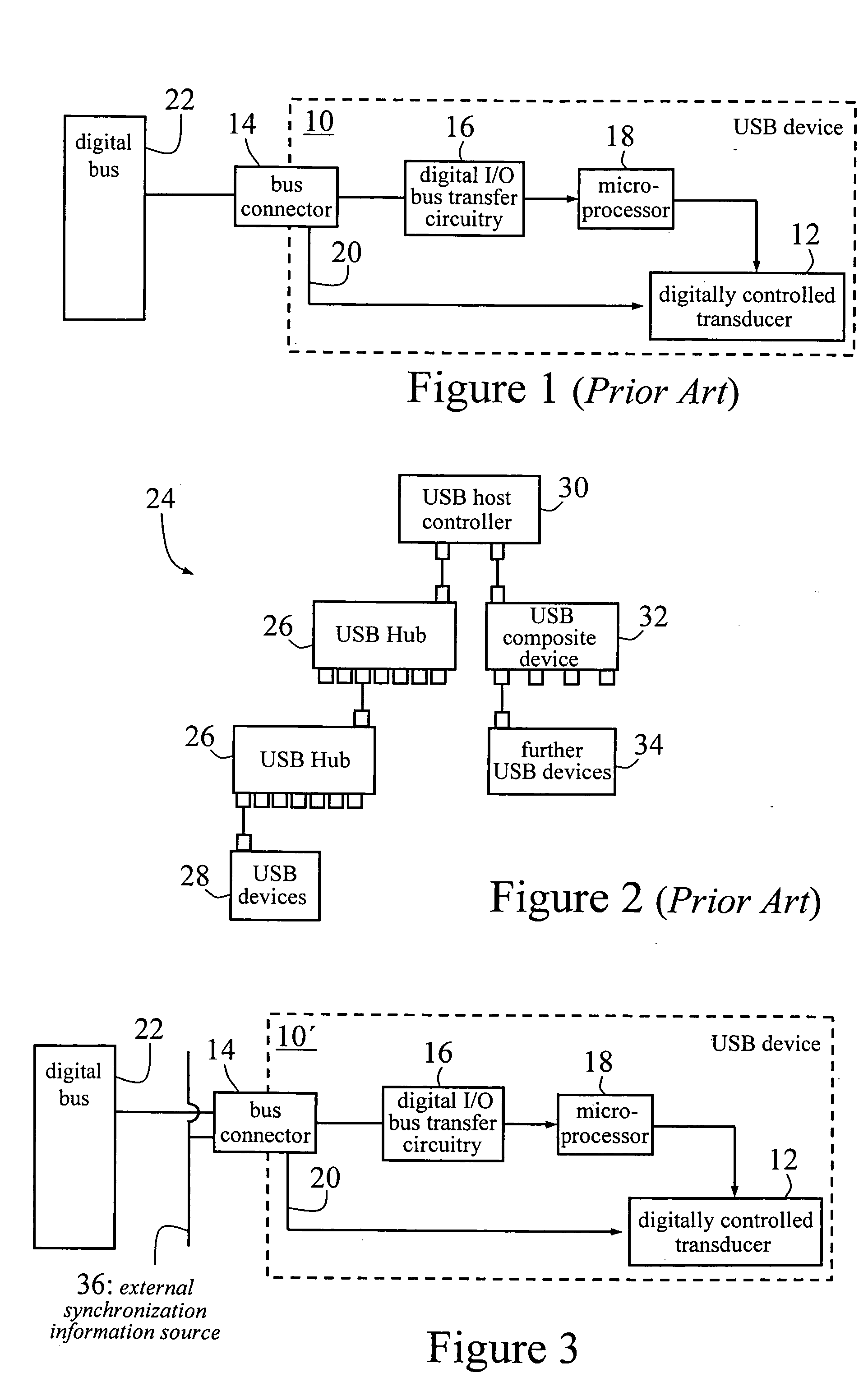
[0019] Thus, it is an aim of this invention to supplement the USB specification by implementing mechanisms which allow any number of USB devices, up to the maximum allowed, to operate i...

Abstract

The invention provides a method and apparatus for providing a synchronized multichannel universal serial bus, the method in one aspect comprising supplementing the signal channels in the USB specification to provide synchronization information from an external source, and in another aspect comprising observing USB traffic and locking a local clock signal of a USB device to a periodic signal contained in USB data traffic, wherein the locking is in respect of phase and/or frequency.

Application Domain

Synchronisation information channelsTime-division multiplex +4

Technology Topic

Traffic volumeUSB +3

Image

  • Synchronized multichannel universal serial bus
  • Synchronized multichannel universal serial bus
  • Synchronized multichannel universal serial bus

Examples

  • Experimental program(3)

Example

Example 1
With no Additional Connector Wiring for Synchronization
[0165] The advantage of a system according to the present invention that does not depend on supplementary synchronization signals is that the devices are not reliant on this information to work in a synchronized manner, and hence ordinary hubs can be used on any stand-alone host. Such a system can be extended to devices that require very accurate synchronization. Thus, an example of such a system is shown in FIG. 7 generally at 96, with upstream USB port 98 and a plurality of back plane hub devices 100, 102 (each, in this example, a 7-port USB hub on back plane 104), which may optionally supply additional power to a plurality of devices 106. Each device 106 may contain a local clock that is frequency and phase locked according to the above-described second embodiment. The back plane 104 and the hubs 100, 102 have the ability to time phase differences between devices 106 (each with random cable length according to the USB specification) by means of device 108 and the techniques described above in the context of the third embodiment. Furthermore, each device 106 contains a phase shift generator for the local clock that operates according to the techniques described above in the context of the third embodiment.

Example

Example 2
[0166] A complex system comprising many synchronous USB devices is shown in FIG. 8 generally at 110. Upstream port 111 receives USB communication from the Host. The system 110 includes a plurality of back planes 112, 113,114 each provided with two back plane hub devices 115. Each back plane hub devices 115 comprises a 7-port USB hub and may optionally supply additional power to a plurality of devices 116. Each device 116 may contain a local clock which is frequency and phase locked according to the above-described second embodiment. Further, first or master back plane 112 also has additional circuitry or logic elements 117 (as in FIG. 7), and has the ability to time phase differences between devices 116 (each with different connection topology) by means of elements 117 and the techniques described above in the context of the third embodiment. Furthermore each device 116 contains a phase shift generator for phase shifting the local clock using the techniques described above in the third embodiment. There may be additional devices and/or hubs and/or back planes connected to downstream ports 118 up to the maximum number of 127 devices defined in the USB specification.
[0167] In addition, the frequency provided by an upstream root hub may be generated by a frequency reference in accordance with the fifth embodiment and any trigger signals may be generated using the approach of the fourth embodiment.

Example

Example 3
Additional Connector Wiring for Synchronization
[0168] The simplest example of such an approach according to the above-described embodiments is achieved by connecting all devices to a common synchronization signal either through a proprietary connector containing USB and synchronization information or through a USB connector, as well as a separate synchronization link. The synchronization information is independent of the USB traffic and can therefore be of arbitrary frequency without any great difficulty. The medium for the synchronization information can be any of wireless, electrical or fiber optic means. FIG. 9 depicts schematically a practical example of such a circuit at 120. The circuit 120 includes, in effect, a pair of circuits each comparable to that of FIG. 7, so that 24 USB devices 122 are connected via 7-port USB hubs 124; these in turn can be connected to a PC via upstream USB ports 126. The USB connection topology has no influence on the synchronization signal, which is supplied separately to the devices by an external clock 128 of frequency Φ. Thus, the devices 122 are connected to the USB and the synchronization signal via either one connector (with connections in addition to the USB requirements) or a standard USB connector plus one or more additional connectors.
[0169] In a more complex form of this example, a back plane containing additional logic elements is used, the logic elements providing accurate control and lock in frequency and phase for all attached devices. In such an arrangement, the back plane logic elements observe USB traffic and generate their own local clock according to the approach of the above-described second and third embodiments. This back plane generated clock is then distributed to each attached USB Device through one or more backplane connectors described above.
[0170] Referring to FIG. 10, therefore, which depicts such an arrangement generally at 130, each device 132 is connected to circuitry 134 through additional connector terminals 136 (electrical, wireless, fiber-optic), which supplement the USB specification. As an example, the circuitry could be located on a back plane 138 to which the various modules are connected. This back plane 138 also contains one or more 7-port USB hubs 140. The circuitry 134 monitors the USB at USB upstream port 142 for a start of frame signal and locks the frequency and phase of its internal clock to this signal (as per the second embodiment). The circuitry 134 can also arbitrarily delay the incoming clock signal, to account for delays due to USB topology (cf. the third embodiment). The internal clock is then made available to each device 132 via the additional connector terminal. In this way, all devices 132 receive a common clock signal to synchronize with.
[0171] It should be noted that in the previously described figures, the synchronization circuitry is drawn separate to the hubs. In another variation, however, shown in FIG. 11 at 150, one hub is a composite device 152 (connected to USB upstream port 154), containing both expansion ports 156 and the synchronization circuitry 158 (which generates local clock signals according to embodiment two and using techniques described in embodiment three to provide phase shift of the local clock to provide synchronization with other devices), which frees up a port 160 of second hub 162 (when compared to the examples discussed above) so that—in the simple configuration shown in FIG. 11—up to 13 devices 164 can be attached.
[0172] It should also be noted also that the USB specification does not restrict the number of ports per hub to be seven. Hence in FIG. 10 there could be one hub 140 that services, for example, 12 ports.
[0173] Modifications within the spirit and scope of the invention may be readily effected by those skilled in the art. It is to be understood, therefore, that this invention is not limited to the particular embodiments described by way of example hereinabove. For the purposes of this specification it should be understood that the word “comprising” means “including but not limited to”, and that the word “comprises” has a corresponding meaning.
[0174] Further, any reference herein to prior art is not intended to imply that such prior art forms or formed a part of the common general knowledge.

PUM

no PUM

Description & Claims & Application Information

We can also present the details of the Description, Claims and Application information to help users get a comprehensive understanding of the technical details of the patent, such as background art, summary of invention, brief description of drawings, description of embodiments, and other original content. On the other hand, users can also determine the specific scope of protection of the technology through the list of claims; as well as understand the changes in the life cycle of the technology with the presentation of the patent timeline. Login to view more.
Why Eureka
Try Eureka