Front-loading medical injector adapted to releasably engage a syringe regardless of the orientation of the syringe with respect to the injector
- Summary
- Abstract
- Description
- Claims
- Application Information
AI Technical Summary
Benefits of technology
Problems solved by technology
Method used
Image
Examples
second embodiment
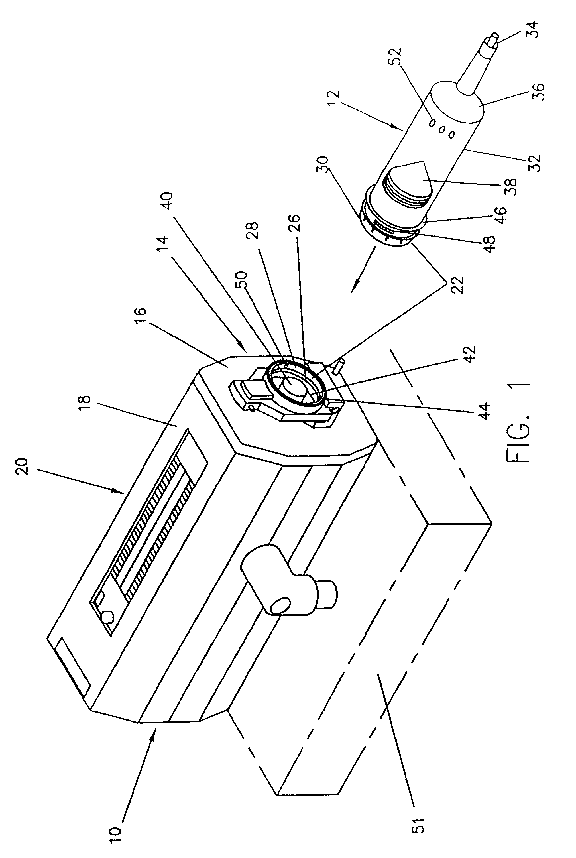
[0230]It is not necessary for tabs 30, 180 to have a V-shaped appearance as illustrated in FIGS. 1 and 4-8, however. It is contemplated for tabs 30 that they have a b-shaped appearance, as illustrated in FIG. 9. When tabs 30 have a b-shaped appearance, they may be formed integrally with the end of syringe 412. Tabs 30, when they have a b-shaped appearance, have bulbous first ends 70 that extend outwardly from second ends 72, which are separated from adjacent tabs 30 by gaps 71 (as best shown in FIGS. 14 and 15). As with first ends 62, first ends 70 engage ledge 29 when syringe has been inserted into injector housing 18. As with first ends 62, reciprocating collar 68 acts upon first ends 70 to disengage them from ledge 29 when syringe 412 is to be removed from injector 20.
[0231]For each of the embodiments of tabs 30 contemplated by the present invention, it is also contemplated that the number of tabs used may be varied while remaining within the scope of the present invention. For e...
embodiment 1700
[0279]FIGS. 42A-42D illustrate an alternate embodiment 1700 of the syringe interface and syringe system 1600 shown in FIGS. 41A-41D. The system 1700 includes a syringe 1512 and a syringe interface 1714. The syringe interface 1714, as best shown in FIGS. 42C and 42D, differs from the syringe interface 1614 in FIGS. 41A-41D in that the retaining members 1732 include pivot ends 1751 located at the ends of the retaining members 1732 remote from the pivot pin 1731. Further, the retaining members 1732 are preferably spring-biased in the “closed” or “engaged” position, as best shown in FIG. 42D, to retain the syringe 1512 within the syringe interface 1714.
[0280]To install the syringe 1512 on the syringe interface 1714, the syringe 1512 is moved downwardly (in the direction of Arrow D in FIG. 42B) into engagement with the retaining members 1732. When the syringe barrel 1516 engages the pivot ends 1751 of the retaining members 1732, the retaining members 1732 are urged apart against the spri...
embodiment 1800
[0282]FIGS. 43A-43I illustrate another alternate embodiment 1800 of the syringe interface and syringe systems 1600, 1700 shown in FIGS. 41A-42D. The system 1800 includes a syringe 1512 and a syringe interface 1814. The syringe interface 1814, as best shown in FIGS. 43B and 43H, differs from the syringe interfaces 1614, 1714 in FIGS. 41A-42D in that the retaining members 1832 include extension members 1855 and chamfers 1857. The extension members 1855 preferably are manipulated to move the retaining members 1832 to an open position (i.e., against the spring force holding the retaining members 1832 in the closed position). The chamfers 1857 are operably engaged by the inclined surface 1526 of the mounting member 1522 of the syringe 1512 to open the retaining members 1832 and allow the syringe 1512 to be axially installed (in the direction of Arrow E in FIG. 43C) on the syringe interface 1814. The remaining structure of the syringe interface 1814 is substantially similar or identical t...
PUM
 Abstract
Description
Claims
Application Information
 - R&D
- Intellectual Property
- Life Sciences
- Materials
- Tech Scout
- Unparalleled Data Quality
- Higher Quality Content
- 60% Fewer Hallucinations
Browse by: Latest US Patents, China's latest patents, Technical Efficacy Thesaurus, Application Domain, Technology Topic, Popular Technical Reports.
© 2025 PatSnap. All rights reserved.Legal|Privacy policy|Modern Slavery Act Transparency Statement|Sitemap|About US| Contact US: help@patsnap.com


