Optical system

a technology of optical systems and optical components, applied in the field of optical systems, can solve the problems of nothing specific about the optical system, etc., and achieve the effects of improving resolving power, reducing the number of optical components, and improving the quality of optical components

Inactive Publication Date: 2009-06-02
OLYMPUS CORP
View PDF4 Cites 5 Cited by
  • Summary
  • Abstract
  • Description
  • Claims
  • Application Information

AI Technical Summary

Benefits of technology

[0006]In view of the state of the prior art as described above, the present invention has for its object the provision of a curved surface image-conversion optical system well fit for all sky cameras, panoramic projectors or the like, which is capable of taking hemispherically curved object images or projecting them as hemispherically curved images with simplified construction, and which is of small format size and improved resolving power with well-corrected aberrations.
[0018]According to the invention as described above, it is possible to obtain a curved surface-conversion optical system which is capable of taking or projecting hemispherically curved object images with simplified construction, and which is of small format size and improved resolving power with well-corrected aberrations.

Problems solved by technology

However, there is nothing specific set forth about the optical system whatsoever.

Method used


Image

  • Optical system
  • Optical system
  • Optical system

Examples


Embodiment Construction

[0036]The optical system of the invention is now explained with reference to its embodiments.

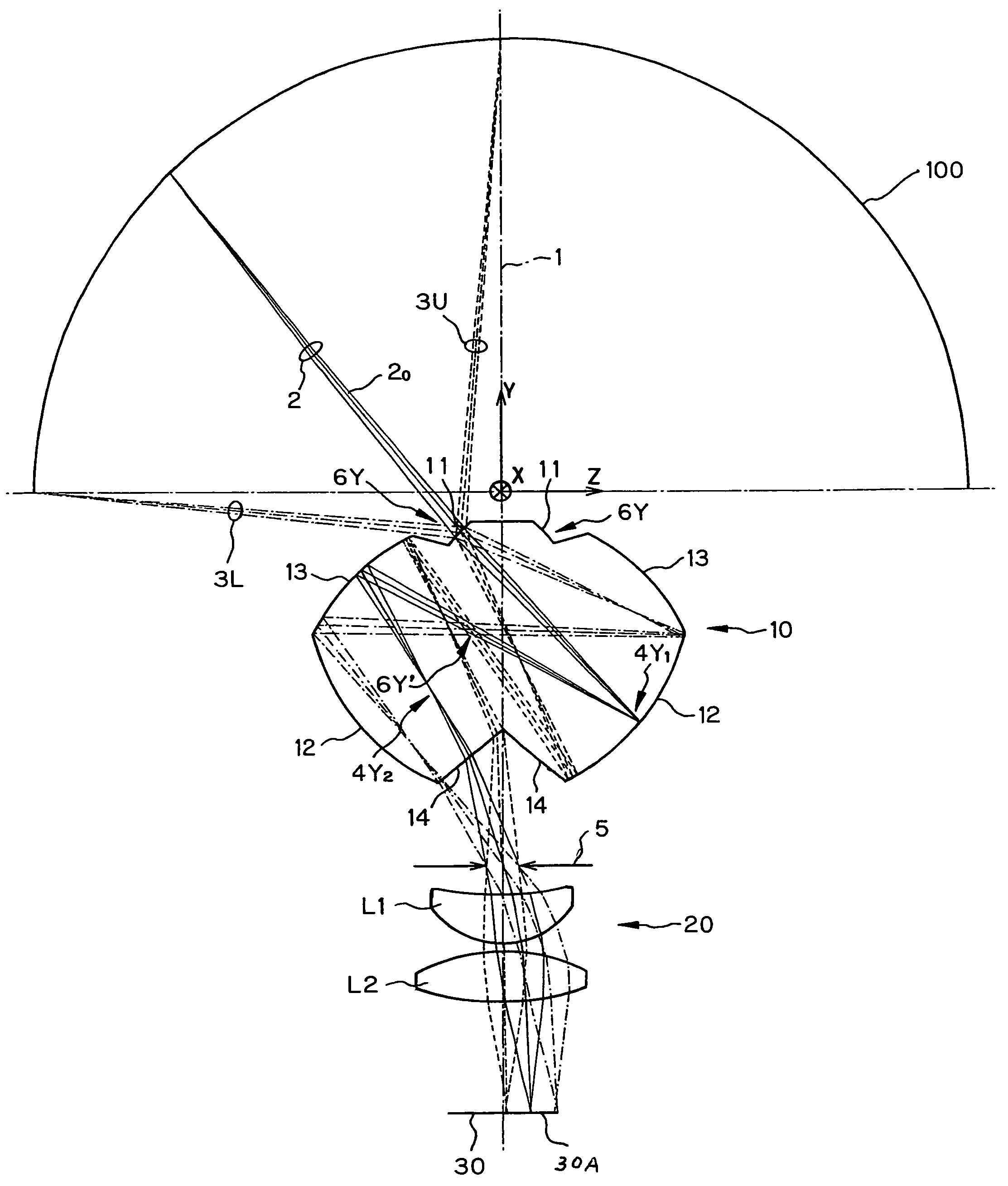
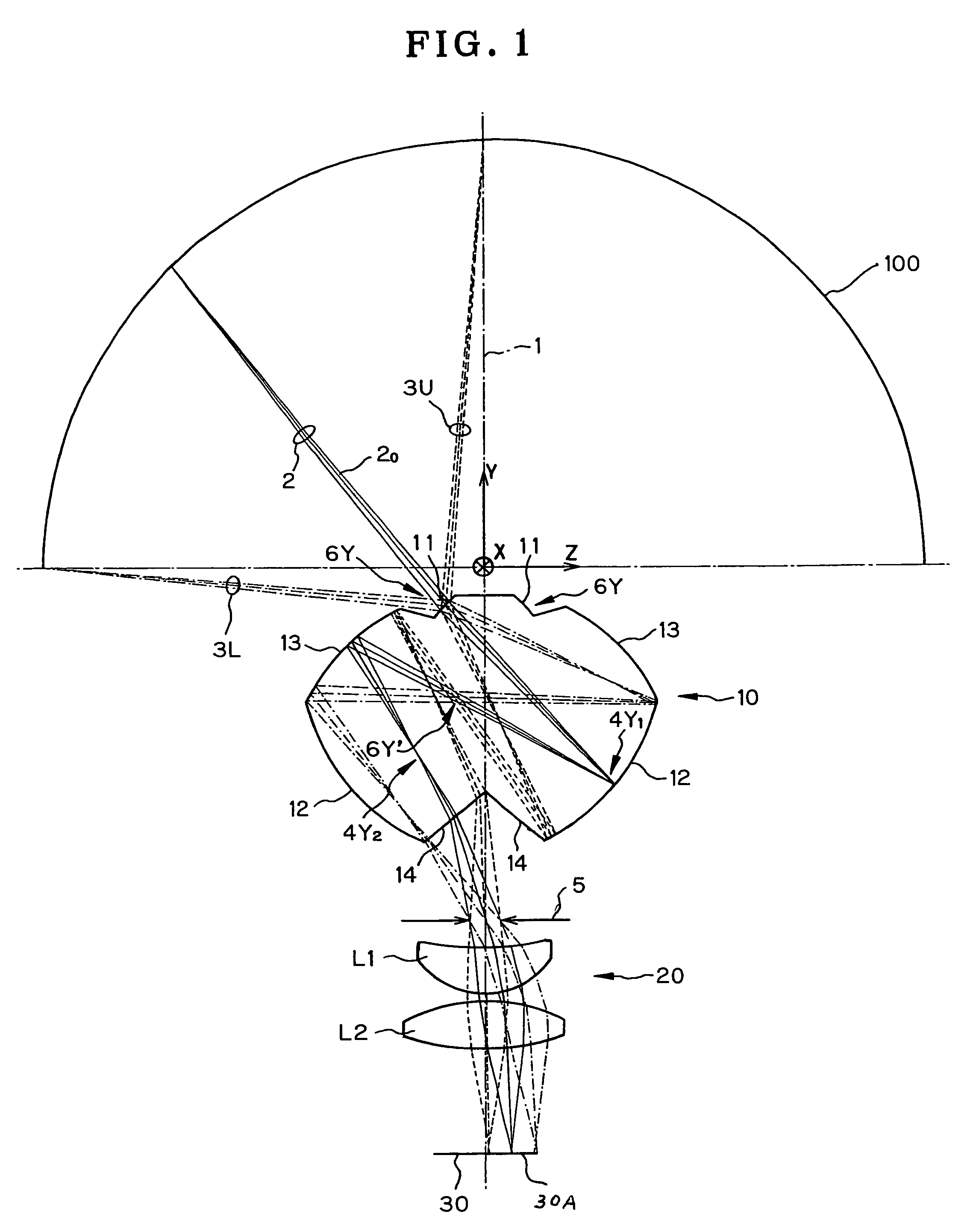
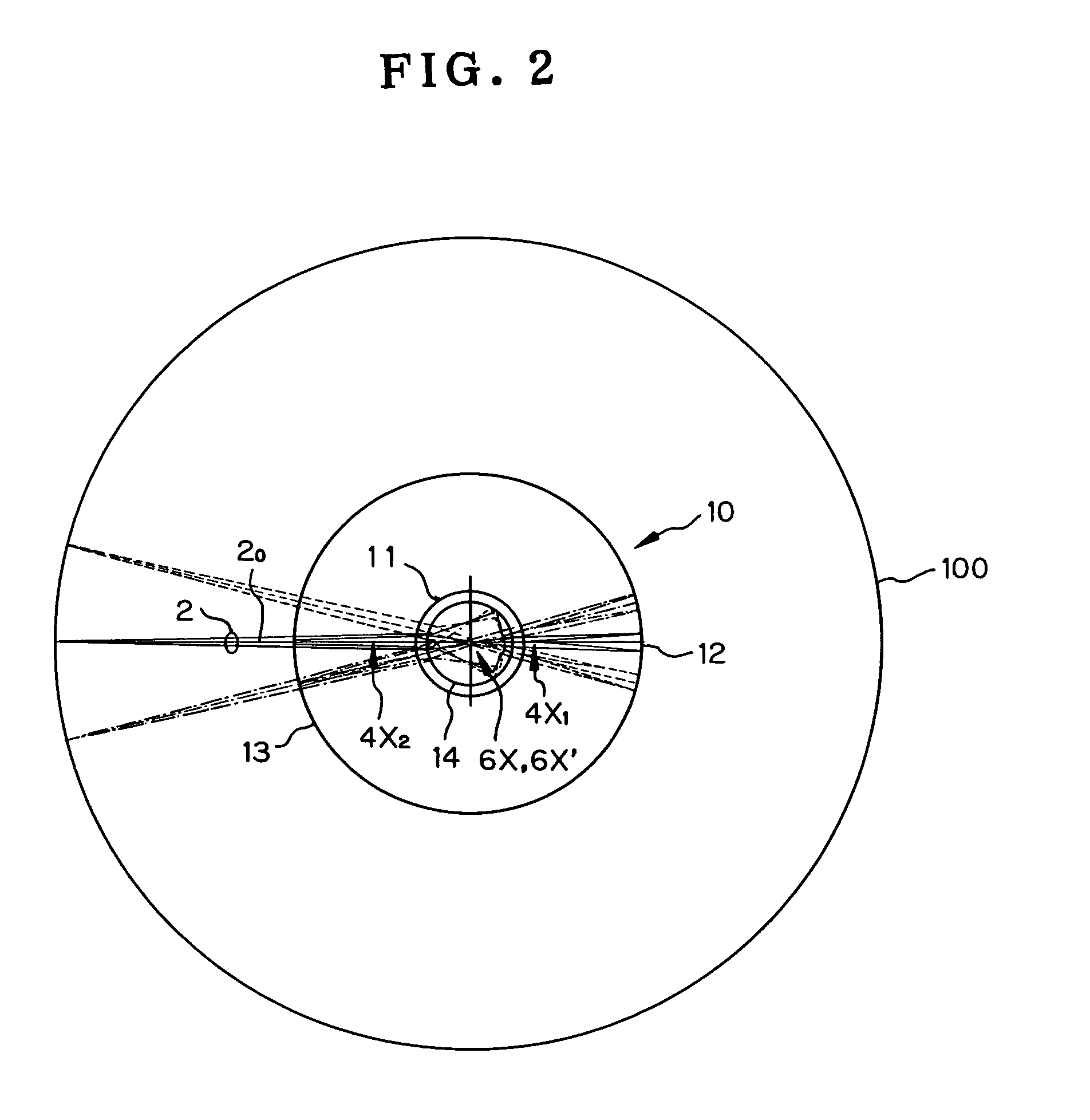
[0037]FIG. 1 is a sectional view of the optical system of Example 1 to be described later, as taken along its center axis (rotationally symmetric axis) 1, and FIG. 2 is a plan view of an optical path through that optical system. With reference to FIGS. 1 and 2, the optical system of the invention is explained. While that optical system will be explained as an image-formation optical system adapted to form an image of a hemispherically curved object, it could be used as a projection optical system adapted to project a hemispherically curved image if the optical path is reversed. In FIG. 2, note that there are an optical path taken by light incident from a direction at an azimuth of 0° and an optical path taken by light incident from a direction at an azimuth of ±14°.

[0038]The optical path of the invention includes a front unit 10 and a rear unit 20, each rotationally symmetric about a center ...


PUM


Abstract

A curved surface image-conversion optical system is configured to take an image of a hemispherically curved object or project it as a curved surface image, which optical system includes a front unit formed of a transparent medium rotationally symmetric about a center axis and having at least two internal reflecting surfaces and two transmitting surfaces, a rear unit that is rotationally symmetric about the center axis and has positive power, and an aperture located coaxially with the center axis. The front unit includes the first transmitting surface through which a light beam from an object point is incident on the front unit, the first reflecting surface for reflecting the transmitted light beam, the second reflecting surface for reflecting the reflected light beam and the second transmitting surface through which the reflected light leaves the transparent medium.

Description

RELATED APPLICATIONS[0001]This application claims the benefit of Japanese Application No. 2005-153760 filed in Japan on May 26, 2005, the contents of which are incorporated herein by reference in their entirety.BACKGROUND OF THE INVENTION[0002]The present invention relates generally to an optical system, and more particularly an objective optical system well fit for all sky cameras or the like adapted to form hemispherical object images on a zonal-form flat image plane and a projection optical system suitable for use with panoramic projectors or the like adapted to project zonal images located on an image plane onto a hemispherically curved surface.[0003]In methods heretofore, when projecting images projected onto a domed screen, a plurality of images projected independently through a plurality of projectors have been put together or projected through a wide-angle optical system such as a fisheye lens.[0004]For instance, Japanese Patent Application Publication No. 2001174713 shows a...

Claims


Application Information

Patent Timeline
Patent Type & Authority Patents(United States)
IPC IPC(8): G02B13/06H04N7/00G02B13/18G02B17/08G03B15/00G03B37/00
CPCG02B13/06
Inventor TOGINO, TAKAYOSHI
Owner OLYMPUS CORP
Why Eureka
Try Eureka