Optical switch with power equalization

a technology applied in the field of optical switches and cross-connects, can solve problems such as reducing the complexity of equalization systems, and achieve the effect of increasing the complexity of switch design

Inactive Publication Date: 2009-06-02
RPX CLEARINGHOUSE
View PDF12 Cites 25 Cited by
  • Summary
  • Abstract
  • Description
  • Claims
  • Application Information

AI Technical Summary

Benefits of technology

[0051]The present invention is directed to providing each signal at the output of a photonic switch with a controllable (e.g., flat) optical power spectrum, while only slightly increasing the complexity of the switch design. The equalization system, or “equalizer”, of the present invention controllably adjusts the optical power of each individual optical signal passing through the photonic

Problems solved by technology

Secondly, wavelength-dependent losses introduced by all the devices in the switch including the WDM devices at the output of the switch are accounted for.
T

Method used


Image

  • Optical switch with power equalization
  • Optical switch with power equalization
  • Optical switch with power equalization

Examples


Embodiment Construction

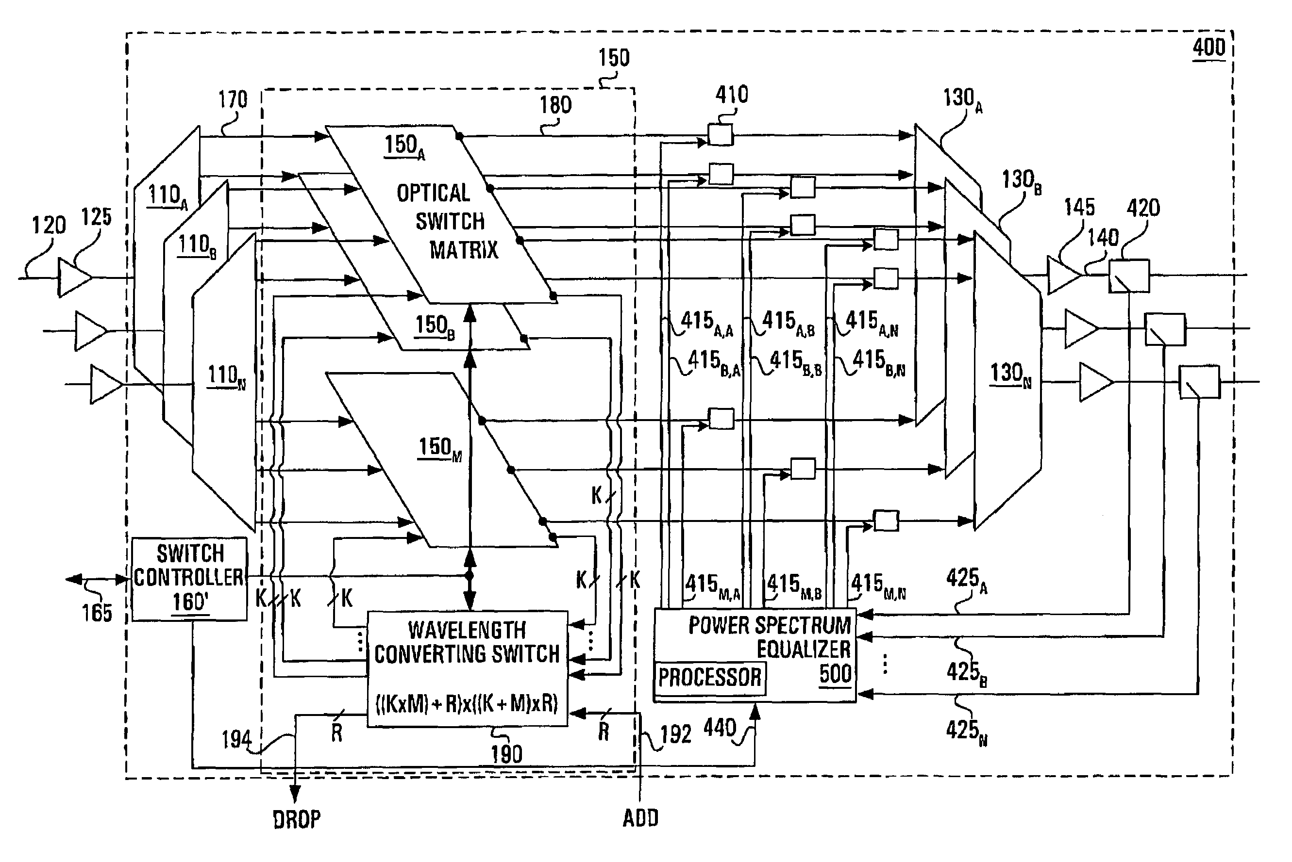
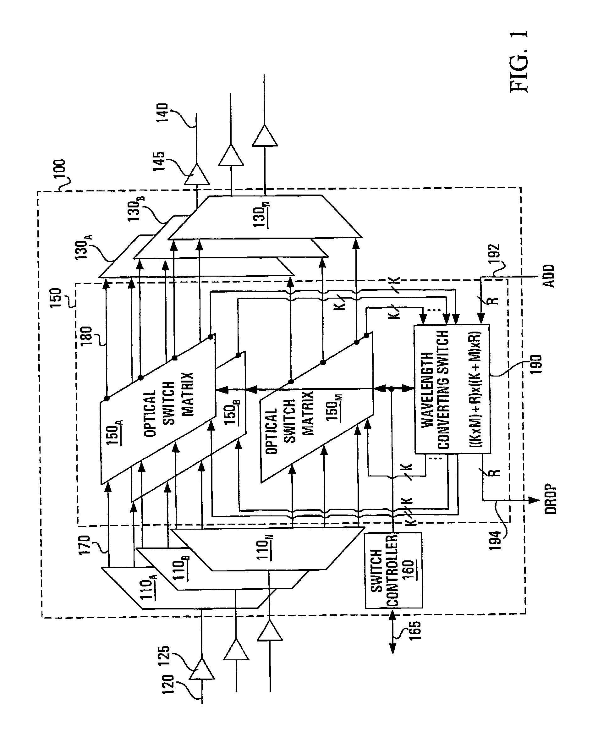
[0090]With reference to FIG. 4, there is shown a photonic switch 400 according to an embodiment of the present invention. The photonic switch 400 resembles the photonic switch 100 of FIG. 1 in that it retains the basic structure including the WDD devices 110A-110N, the WDM devices 130A-130N and the photonic switch core 150.

[0091]The photonic switch 400 of the invention additionally comprises a plurality (M×N) of variable optical intensity controllers (VOICs) 410 respectively positioned in each of the demuxed switched optical paths 180. Thus, each of the VOICs 410 is associated with a respective switched individual optical carrier signal that emerges from the photonic switch core 150 along a respective one of the demuxed switched optical paths 180.

[0092]The VOICs 410 are used for providing intensity control in the form of either attenuation or amplification. Thus, each of the VOICs 410 can either be a variable optical attenuator or a variable optical amplifier, depending on the opera...


PUM


Abstract

An optical intensity control system for use with an optical switch providing individual signal paths between input and output ports. The system has a optical splitters connectable to output multiplexers of the switch and also has variable optical intensity controllers (VOICs) for insertion into the individual signal paths. The VOICs individually control the intensity of optical signals present in the signal paths in accordance with intensity control signals. An equalizer is connected to the splitters and to the VOICS, for producing an estimate of the optical power of each individual switched optical signal and generating the intensity control signals. The equalizer is adapted to controllably isolate individual switched optical signals. In this way, individual and independent control of the power on each optical channel is provided, wavelength-dependent losses introduced by all the devices in the switch including the WDM devices at the output of the switch are accounted for and one optical coupler is required for each output optical fiber. Coarse equalization may be provided for each multiplexed optical signal either at the switch input or output, permitting a reduction in the dynamic range over which the VOICs inside the switch are required to operate.

Description

CROSS-REFERENCES TO RELATED APPLICATIONS[0001]The present application is related in subject matter to co-pending U.S. patent application Ser. No. 09 / 511,065 to Graves et al., entitled “Switch for Optical Signals”, filed on Feb. 23, 2000, assigned to the assignee of the present invention and hereby incorporated by reference herein in its entirety.[0002]The present application is also related in subject matter to the co-pending U.S. patent application entitled “Optical Switch with Connection Verification” to Graves et al., filed on even date, assigned to the assignee of the present invention and hereby incorporated by reference herein in its entirety.FIELD OF THE INVENTION[0003]The present invention relates generally to systems used for switching optical wavelength channels in a wavelength division multiplexed (WDM) network and, more particularly, to optical switches and cross-connects which are required to be equipped with power equalization functionality for controlling the power of...

Claims


Application Information

Patent Timeline
IPC IPC(8): H04J14/00H04Q11/00
CPCH04Q11/0005H04Q2011/0015H04Q2011/0083H04Q2011/0049H04Q2011/0016
Inventor GRAVES, ALAN FRANKGERALD, JOHNBRYANT, ANDREW JOHN
Owner RPX CLEARINGHOUSE
Why Eureka
Try Eureka