Needle device comprising a plurality of needles

a technology of needles and needles, which is applied in the field of needle devices comprising a plurality of needles, can solve the problems of inability to meet the needs of patients, the overall cost of the use of this type of devices will have to be compared, and the initial cost of the pump, so as to improve the quality of treatment, reduce the cost of disposable devices, and improve the effect of treatment quality

Inactive Publication Date: 2009-06-09
NOVO NORDISK AS
View PDF24 Cites 78 Cited by
  • Summary
  • Abstract
  • Description
  • Claims
  • Application Information

AI Technical Summary

Benefits of technology

[0024]Having regard to the above-identified problems, it is an object of the present invention to provide systems and devices by which the costs associated with the use of disposable, subcutaneous devices can be lowered allowing more patients to utilize these devices and to thereby improve the quality of treatment. In this context, the term subcutaneous device is used to identify devices which are based on the introduction of a subcutaneous element through the skin of a subject, e.g. an infusion needle or a needle-introduced sensor element.

Problems solved by technology

However, the above-described deterioration is reflected in the fact that beta cell stimulators will eventually fail to stimulate the cell, and the patient has to be treated with insulin, either as mono therapy, or in combination with oral medication in order to improve glucose control.
The second mode is infusion pump therapy, which entails the purchase of a relatively expensive pump, for which reason the initial cost of the pump is often a barrier to this type of therapy.
Especially, the overall costs for the use of this type of devices will have to be compared with traditional injection therapy or traditional pump treatment.
In principle, such systems have been known for more than two decades, see for example U.S. Pat. No. 4,245,634 which discloses an artificial beta cell for regulating blood glucose concentration in a subject by continuously analyzing blood from the patient and deriving a computer output signal to drive a pump which infuses insulin at a rate corresponding to the signal, however, mainly due to problems associated with the glucose sensors such systems have until today not been very successful.
When a sensor element is introduced subcutaneously, the body responds to the element as an insult and produces a specialized biochemical and cellular response which may lead to the development of a foreign body capsule around the implant and consequently may reduce the flux of glucose to the sensor.
In addition to the costs associated with replacement of sensor elements, also the replacement as such may be considered cumbersome by the patient, e.g. the old sensor would have to be removed and a new mounted and actuated.
Especially, the overall costs for the use of this type of system will have to be compared with traditional measuring of values, e.g. blood glucose measuring based on needle puncture.

Method used


Image

  • Needle device comprising a plurality of needles
  • Needle device comprising a plurality of needles
  • Needle device comprising a plurality of needles

Examples


first embodiment

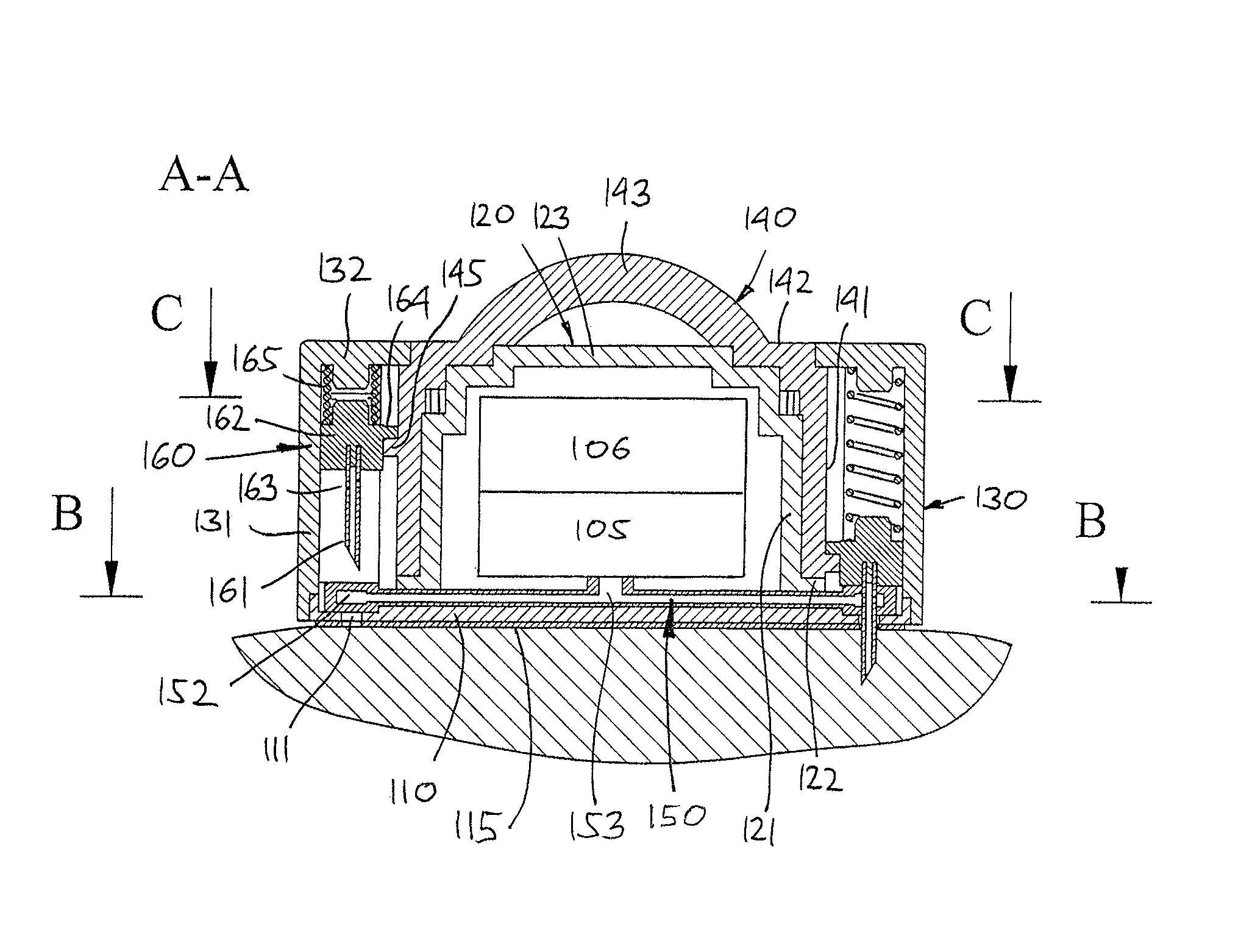
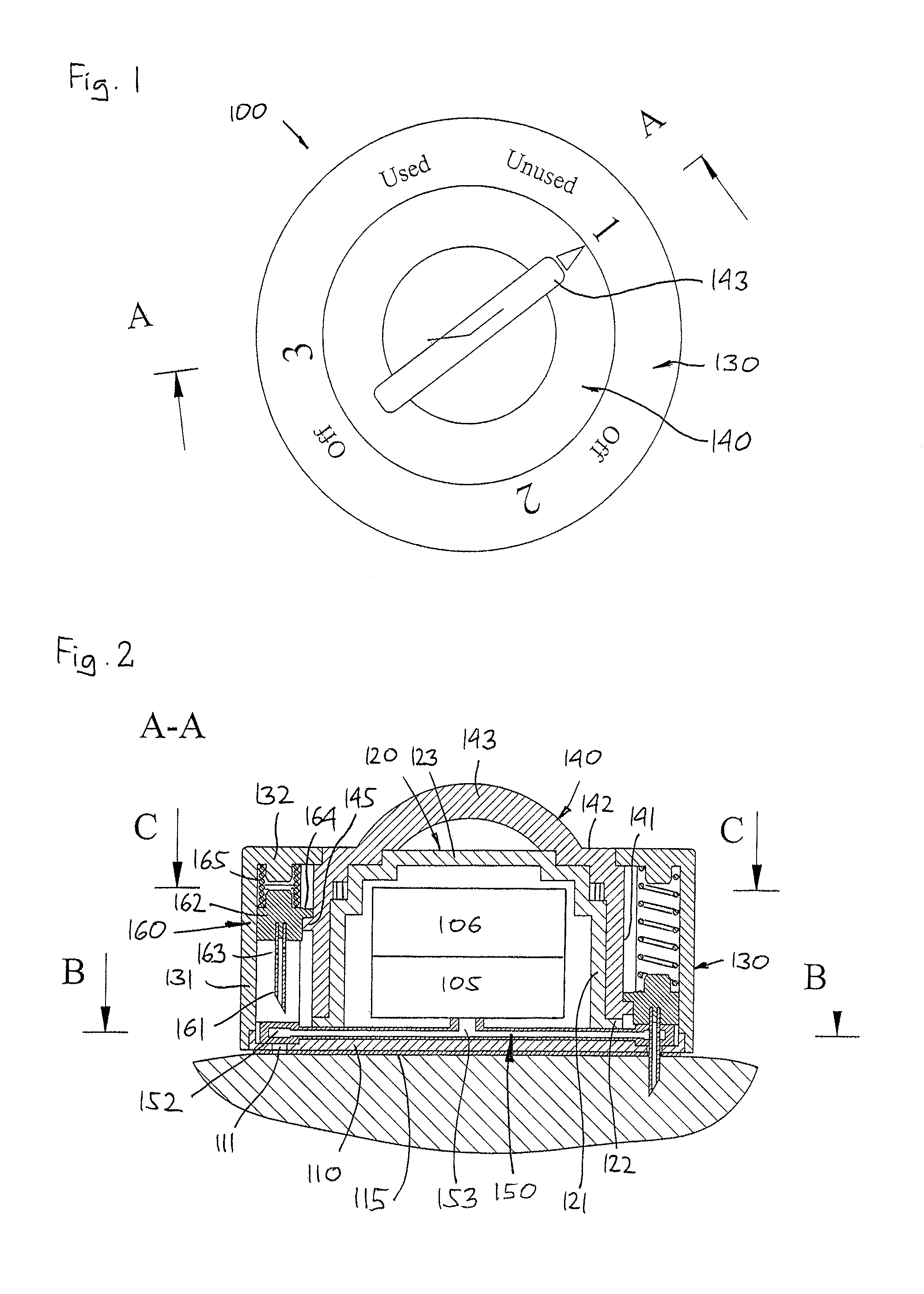
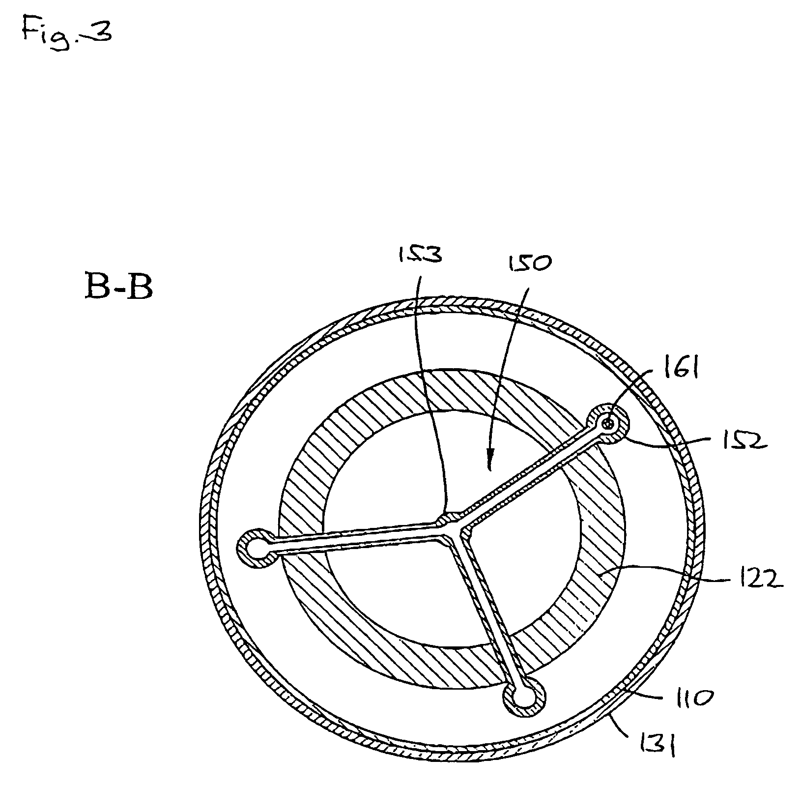
[0067]With reference to FIGS. 1-5 a needle device will be described. It is to be noted that in FIGS. 3 and 5 the sectional views correspond to the full device and not the sectional device of FIG. 2. More specifically, the needle device 100 comprises a base plate member 110, a core member 120 connected to the base plate member, a housing member 130 also connected to the base plate member, and a moveable control member 140, the members in combination forming a device having a generally cylindrical configuration.

[0068]The base plate member comprises a lower surface with adhesive means 115 adapted for releasable application to the skin of a subject, an upper surface, and three openings 111. The core member is in the form of a downwardly open hollow cylindrical body having a cylindrical wall 121 with an inner and an outer surface and in the vicinity of the lower free edge an outwardly projecting rim 122, and an upper wall 123 having two circumferentially arranged stepped portions. The co...

second embodiment

[0072]As appears from FIGS. 2 and 5, each needle carrier is guided in combination by the guide structure of the housing member and the outer wall surface of the control member, with the lower surface of the steering pin being supported on the upper surface of the steering guide. Between the upper surface of the carrier member and the lover surface of the upper circumferential flange portion 132 a biasing member 165 is arranged providing a downwardly directed force on the carrier member. In the shown embodiment the biasing member is in the form of a helical spring held in place by projections formed on the carrier member respectively the flange portion, however, the biasing means could also be in the form of a leaf spring, a compressible foam member, a gas spring or any other suitable spring means (this also applies to the biasing means of the second embodiment).

[0073]By this arrangement the needle assemblies are only allowed to move perpendicular relative to the general “horizontal”...


PUM


Abstract

A needle device comprises a housing, a base portion having a mounting surface adapted for application to the skin of a patient, and a plurality of needles. Each needle comprises a distal pointed end adapted to penetrate the skin of the subject, and has a first position in which the distal end is retracted relative to the mounting surface, and a second position in which the distal end projects from the mounting surface. The needles are arranged such that at least one needle can be moved from its first to its second position, or vice versa, with at least one other needle not performing the same movement. In this way a plurality of needles can be introduced transcutaneously at a selected site within the body of a subject. The device may comprise a common fluid conduit with at least two of the needles having a proximal opening to be arranged in fluid communication with the common fluid conduit.

Description

CROSS REFERENCE TO RELATED APPLICATIONS[0001]This application claims priority under 35 U.S.C. 119 of Danish application no. PA 2002 01494 filed Oct. 7, 2002 and U.S. provisional application No. 60 / 419,308 filed Oct. 17, 2002, the contents of both are fully incorporated herein by reference.[0002]The present invention generally relates to the insertion of needles. More specifically, the invention relates to a needle device for individually introducing a plurality of needles transcutaneously at a selected site within the body of a subject. Especially, the invention relates to insertion of infusion needles for the infusion of a drug, to insertion of needle-formed sensors, as well as to insertion of insertion needles for easy transcutaneous placement of a transcutaneous device such as a sensor.BACKGROUND OF THE INVENTION[0003]In the disclosure of the present invention reference is mostly made to the treatment of diabetes by injection or infusion of insulin, however, this is only a prefer...

Claims


Application Information

Patent Timeline
Patent Type & Authority Patents(United States)
IPC IPC(8): A61M5/00A61B5/00A61B5/15A61M5/142A61M5/158A61M5/172A61N1/05A61N1/30
CPCA61B5/1411A61B5/14532A61B5/15146A61B5/4839A61B5/6849A61M5/14248A61M5/158A61M5/1723A61B5/0002A61M5/003A61M2005/14252A61M2005/1426A61M2005/14268A61M2005/1581A61M2005/1585A61M2230/201A61N1/05A61N1/0502A61N1/30A61M2230/005A61B5/1518A61B5/150022A61B5/150389A61B5/15087A61B5/15117A61B5/157A61B5/150503A61B5/150824A61B5/15163
Inventor BENGTSSON, HENRIK
Owner NOVO NORDISK AS
Why Eureka
Try Eureka