
Exhaust fan assembly having H-out nozzle

a technology of exhaust fan and nozzle, which is applied in the direction of machines/engines, mechanical equipment, light and heating apparatus, etc., can solve the problems of reducing the separation desired between the release point, reducing the amount of ambient air entrainment, and reducing the amount of ambient air so as to improve the entrainment of ambient air, improve the dilution and plume height of exhaust air, and improve the effect of dispersing th

Active Publication Date: 2009-06-16
GREENHECK FAN
View PDF62 Cites 13 Cited by
  • Summary
  • Abstract
  • Description
  • Claims
  • Application Information

AI Technical Summary

Benefits of technology

This configuration enhances air entrainment by 10-20% over conventional nozzles, increasing dilution and flow volume, leading to improved dispersion of exhaust air away from buildings, reducing maintenance and cost.

Problems solved by technology

In areas such as laboratories and kitchens, fumes are often produced that have an unpleasant odor or are otherwise undesirable.
However, these exhaust stacks are expensive to construct and maintain and are generally considered unsightly.
By diluting the undesirable air before release into the surrounding environment, these systems reduce the amount of separation desired between the release point and the surrounding environment.
While these “stack-less” exhaust systems are desirable, they typically have associated maintenance costs and may not be suitable for a given application without significant adaptation for the particular performance specifications of the given application.
For example, in some circumstances, a particular fan arrangement, that is, motor size, blade configuration, and / or nozzle configuration, may not achieve and sustain flow characteristics to achieve the plume height and flow volume necessary to exhaust the air a sufficient distance from the building and surrounding environment.
A drawback with the disclosed nozzle is that the air exiting the nozzle moves in a generally inward direction toward the vertical centerline of the windband above the nozzle due to the inward taper of the nozzle walls.
This does not optimally entrain ambient air with the building exhaust air, possibly because the periphery of the exiting air is not sufficiently turbulent or because the area of the flow path is not large enough.

Method used


Image

  • Exhaust fan assembly having H-out nozzle
  • Exhaust fan assembly having H-out nozzle
  • Exhaust fan assembly having H-out nozzle

Examples


Embodiment Construction

)

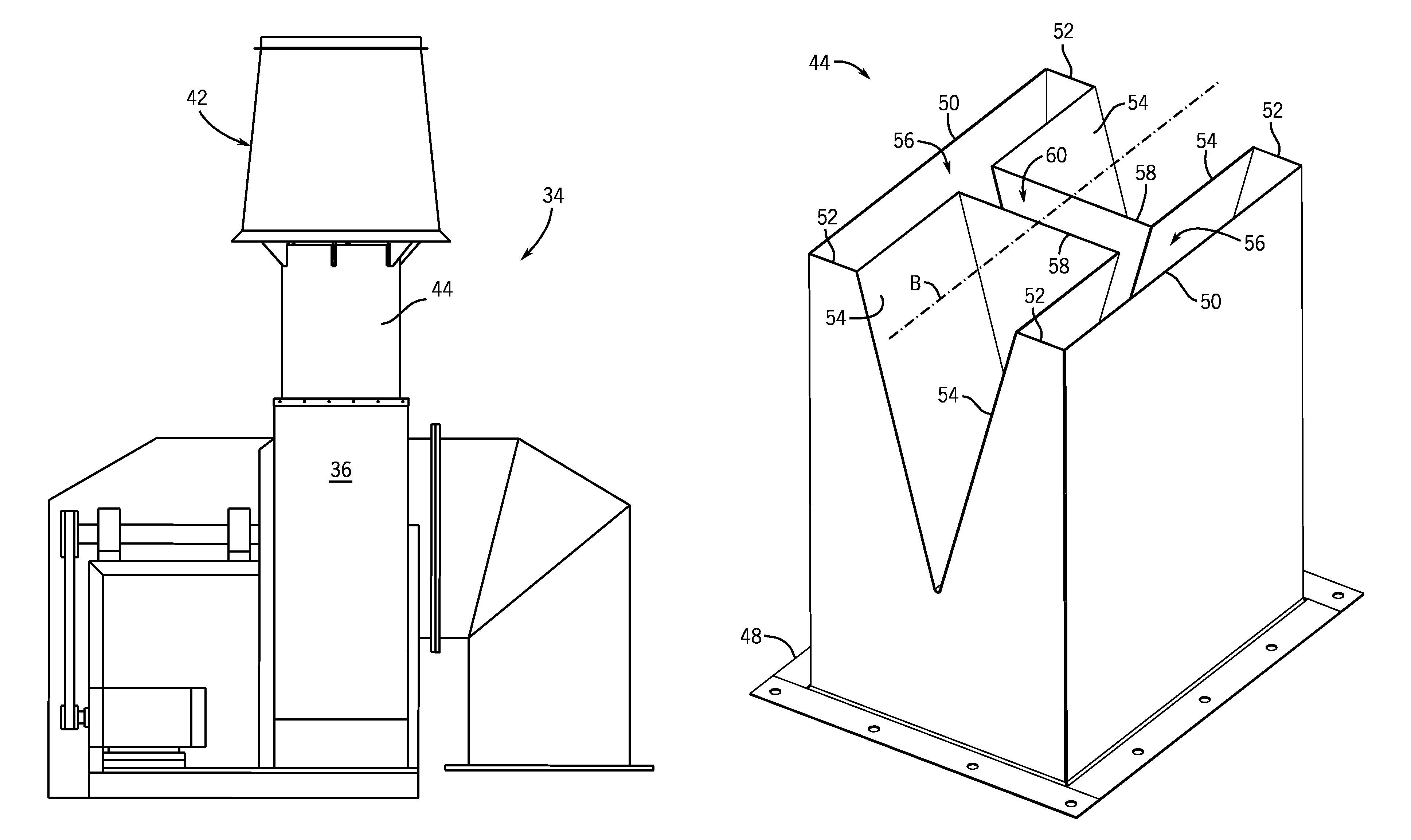
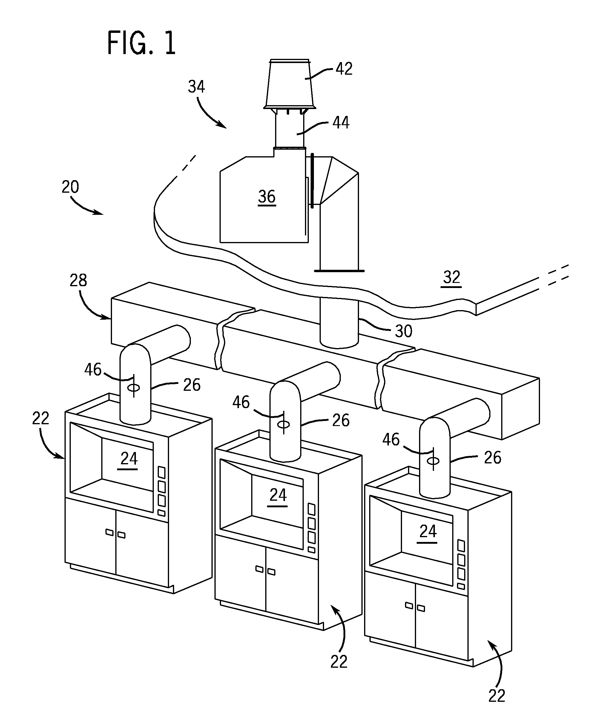
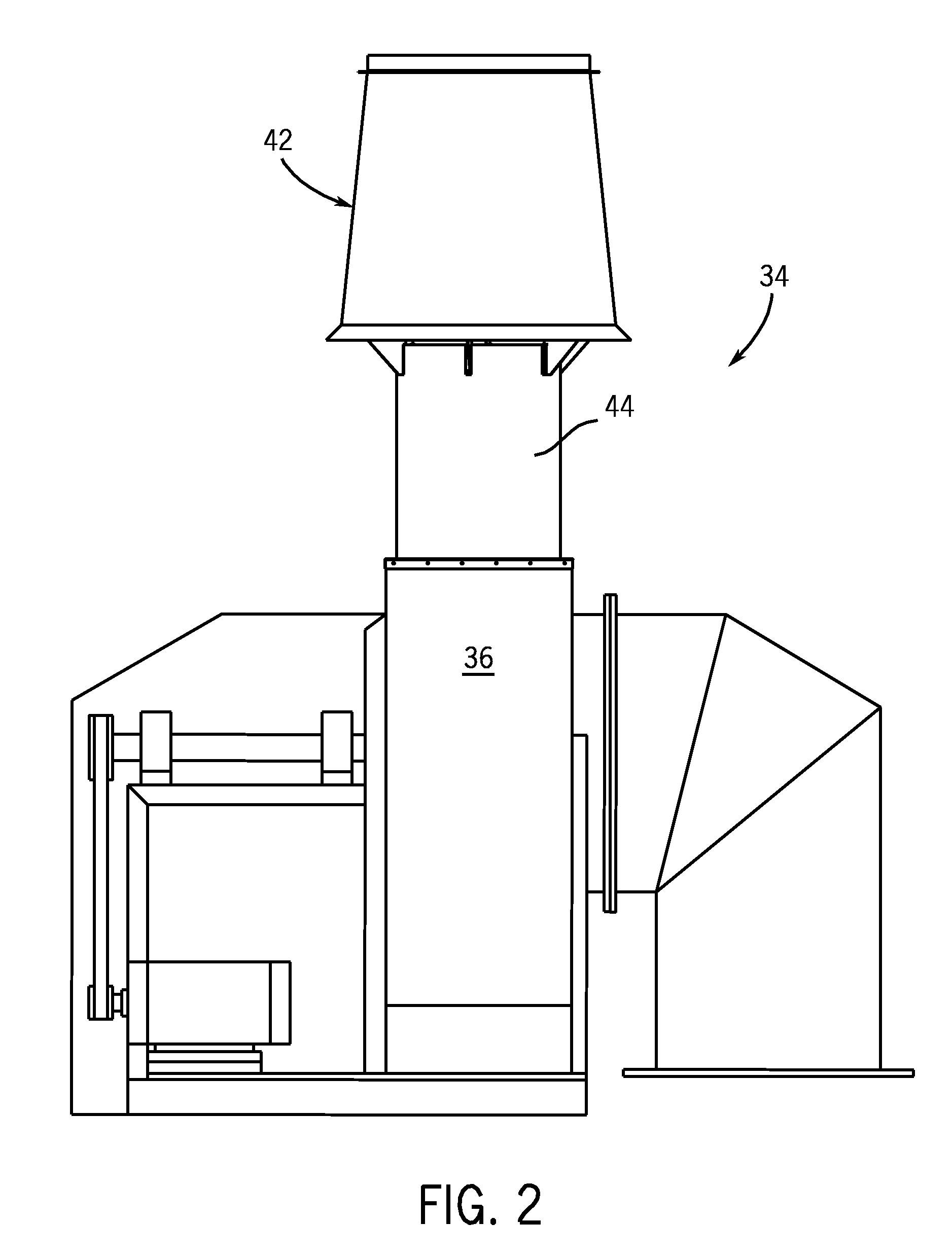
[0023]Referring to FIG. 1, a building ventilation system 20 is shown that includes a plurality of fume hoods 22 of the type often installed in commercial kitchens, laboratories, manufacturing facilities, or other similar locations where fumes or other undesirable air may be generated. In the illustrated example, each fume hood 22 includes a chamber 24 that is open at a front of the hood 22 for receiving surrounding air. While the chambers 24 are shown as an enclosed space, it is contemplated that the present invention may be used with any of a variety of ventilation systems 20, such as traditional ceiling-mounted fume hoods or the like. A conduit 26 extends from each hood 22 and forms a passage from each hood 22 to a manifold 28. The manifold 28 is connected to a riser 30 that extends upwards to a roof 32 or other exterior surface of the building. The riser 30 is, in turn, connected to an exhaust assembly 34 that is mounted on top of the roof 32 and extends upwards away from the ro...


PUM


Abstract

An exhaust system for expelling air from a building includes an outlet nozzle that improves entrainment of ambient air with the building exhaust air. The improved air entrainment results in increased exhaust air dilution and plume height to better disperse the exhaust air away from the building. The nozzle has an H-shaped outlet configuration with two lateral outlet sections joined by a central transverse outlet section. The nozzle has a pair of outer lateral walls, a pair of outer transverse walls, and a pair of sloped inner lateral walls that angle outwards from near an inlet end of the nozzle towards corresponding outer lateral walls. The nozzle can be part of the exhaust system at the outlet side of the exhaust fan within a windband that aids in entraining ambient air with the exhaust air exiting the nozzle.

Description

CROSS-REFERENCE TO RELATED APPLICATIONS[0001]This application claims priority to U.S. Provisional Application No. 60 / 588,074 filed on Jul. 15, 2004, and U.S. Provisional Application No. 60 / 625,220 filed Nov. 5, 2004, the disclosure of each of which is hereby incorporated by reference as if set forth in its entirety herein.BACKGROUND OF THE INVENTION[0002]The present invention relates generally to exhaust nozzles, and more particularly to nozzles for use with exhaust systems that evacuate fumes or otherwise draw undesirable air from within a building or enclosure.[0003]There are many different types of exhaust systems for buildings and enclosed spaces. In areas such as laboratories and kitchens, fumes are often produced that have an unpleasant odor or are otherwise undesirable. It is common to outfit such environments with exhaust systems that draw the fumes from the building and dispel them through an exhaust port that is typically located on an external wall or roof of the building...

Claims


Application Information

Patent Timeline
Patent Type & Authority Patents(United States)
IPC IPC(8): F23L17/02F23L17/00
CPCB08B15/002F04F5/16
Inventor SELIGER, MICHAEL G.ENZENROTH, JOHN W.
Owner GREENHECK FAN
Learn More