Centrifuge

a centrifuge and belt drive technology, applied in the direction of centrifuges, motors/generators/converter stoppers, dynamo-electric converter control, etc., can solve the problems of increasing the height of the centrifuge, difficult to use, and difficult to precisely control the rotation speed of the rotor b>1

Inactive Publication Date: 2009-06-16
KOKI HLDG CO LTD
View PDF9 Cites 51 Cited by
  • Summary
  • Abstract
  • Description
  • Claims
  • Application Information

AI Technical Summary

Benefits of technology

[0019]The invention has been made in view of the above-mentioned problems. It is an object of the invention to precisely control the rotation speed of the rotor independently of the slippage amount of the belt and control the motor in an optimal manner.
[0021]According to the invention, it is possible to precisely control the rotation speed of the rotor independently of variations in the slippage amount of the belt and control the motor in an optimal manner.

Problems solved by technology

Meanwhile, when the desktop type centrifuge is arranged in the same manner (i.e., in the direct-driven manner) as the floor install type centrifuge in order to mount the centrifuge on the platform, the height of the centrifuge increases, thereby making it difficult to use.
Therefore, since the slippage S of the belt 11 is not considered when the rotor rotation speed Nr is deduced on the basis of Equation 2, a varying error may generate depending on the used load, thereby making it difficult to precisely control the rotation speed of the rotor 1.
The application voltage V varies depending on the difference Ne between the target motor rotation speed Nm* and the motor rotation speed Nm, independently of the rotor rotation speed Nr, thereby making it difficult to precisely control the rotation speed of the rotor 1.
Similarly, in the case of using a brushless DC motor, a control item includes a phase difference between stator excitation and direction of magnetic pole of rotator in the motor 2, i.e., a lead angle θ and the application voltage V. Therefore, the control is performed only on the basis of the motor rotation speed Nm, thereby making it difficult to precisely control the rotation speed of the rotor 1.
Accordingly, it is difficult to control the motor 2 in an optimal manner.

Method used


Image

  • Centrifuge
  • Centrifuge
  • Centrifuge

Examples


Embodiment Construction

[0035]Hereinafter, embodiments of the invention will be described with reference to drawings. Those elements having a similar function will be denoted by the same reference numerals throughout the entire drawings, and redundant description will be omitted. Moreover, those elements having a function similar to those in the background art will be denoted by the same reference numerals.

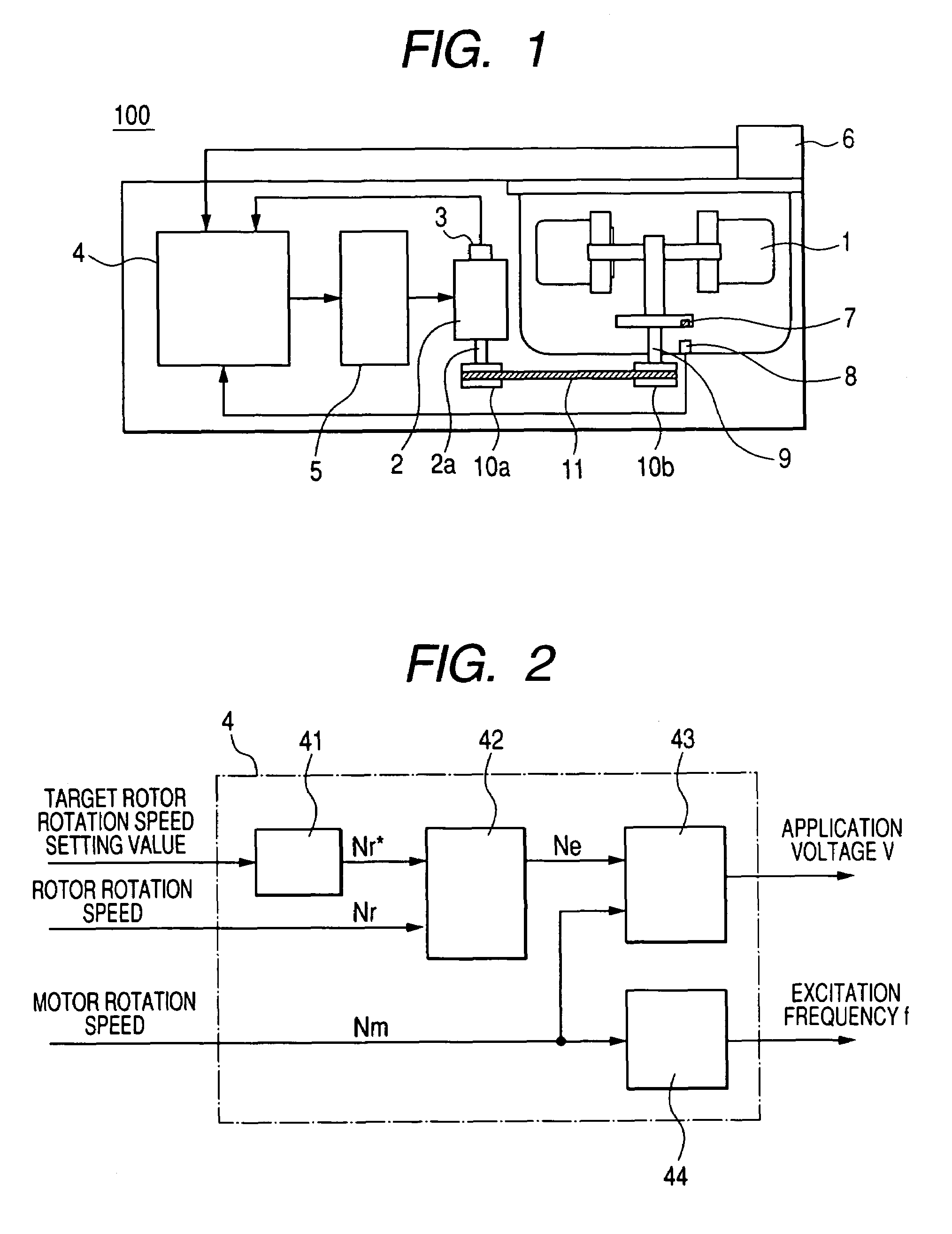
[0036]First, the entire structure of the belt-driven centrifuge according to the invention will be described with reference to FIG. 1. The belt-driven centrifuge 100 includes a rotor 1 containing a sample for separation, a rotor rotation shaft 9 having one end connected to the rotor 1 and the other end fixed to a rotor pulley 10b, a rotor speed detector 8 detecting a rotation speed signal of the rotor output from a rotor signal generator 7 provided to the rotor 1, a motor 2 serving as a driving source of the rotor 1 and having a motor rotation shaft 2a fixed to a motor pulley 10a, a belt 11 engaged with ...


PUM


Abstract

A centrifuge including: a rotor rotating with a sample contained therein; a rotating shaft rotatably engaged with the rotor; a motor rotating the rotor and the rotating shaft; a belt transmitting rotational force of the motor to the rotating shaft; a rotor speed detecting unit detecting a rotation speed of the rotor; a motor speed detecting unit detecting a rotation speed of the motor; and a control unit controlling the motor, wherein the control unit calculates a signal for controlling the rotation speed of the rotor on the basis of a signal from the rotor speed detecting unit and controls the motor on the basis of a signal from the motor speed detecting unit and the calculated signal.

Description

BACKGROUND[0001]1. Technical Field[0002]The present invention relates to a belt-driven centrifuge in which rotation force of a motor is transmitted to a rotor by means of a force transmission member such as a belt.[0003]2. Related Art[0004]A centrifuge rotates a rotor containing a sample for separation in a tube or a bottle at a high speed by a drive unit such as a motor so as to separate and refine the sample contained in the rotor. The rotation speed of the rotor varies depending on the usage of the centrifuge. The centrifuge has a wide range of product line from relatively low speed centrifuges having a maximum rotation speed of several thousand rpm to relatively high speed centrifuges having a maximum rotation speed of 150,000 rpm.[0005]The centrifuge can be classified into a floor install type centrifuge used in a state that the centrifuge is fixed on a floor and a desktop type centrifuge used in a state that the centrifuge is installed on a platform. In the floor install type ...

Claims


Application Information

Patent Timeline
Patent Type & Authority Patents(United States)
IPC IPC(8): H02P7/00B04B5/02H02P6/06H02P6/08H02P23/07H02P23/16H02P27/06
CPCB04B9/10
Inventor TAKAHASHI, HIROYUKIFUJIMAKI, TAKAHIROOYAMA, HISANOBU
Owner KOKI HLDG CO LTD
Why Eureka
Try Eureka