Thermal transfer devices with fluid-porous thermally conductive core

a technology of thermal conductors and transfer devices, which is applied in the direction of insulated conductors, semiconductor/solid-state device details, cables, etc., can solve the problems of insufficient effectiveness of conventional cooling methods, inconvenient pumping, and injurious to equipment or its environment, so as to reduce the size and power of the pump, and facilitate fluid push. , the effect of less pressure drop

Inactive Publication Date: 2009-06-23
PAR TECH
View PDF38 Cites 15 Cited by
  • Summary
  • Abstract
  • Description
  • Claims
  • Application Information

AI Technical Summary

Benefits of technology

[0013]The fluid-porous, thermally-conductive core structure can comprise, for example, either wires or expanded metal which are configured into a mesh, or a fluid-porous metallic wool. In some embodiments, the thermal core takes the form of a thermal mesh structure comprising woven wires, and particularly woven wires which are fused by diffusion bonding into a mesh. For example, the wires comprising the wire mesh structure can be fused as a diffusion bond is formed between tangent metal surfaces when enough atoms or molecules migrate between them to create new metallurgical grains which bridge the gap. The diffusion bonding of the wires provides the wire mesh structure with many and appropriately sized interstices, making it easier to push the fluid through the thermal transfer device and thereby significantly reducing the size and power of the pump which pushes the fluid.
[0014]The core, whether comprised of an expanded mesh or a diffusion bonded mesh, has greater numbers of fluidic paths and thus far less pressure drop than a microchannel device. Further, the thermal transfer efficiency is increased due to the fact that the mesh structure has such a large surface area, up to five to ten times more that a standard microchannel heat sink.
[0016]In embodiments in which wires of the thermal mesh structure are fused in a diffusion bonding process, the wire mesh structure can be fused to either or both of the thermal transfer base or the housing cover during a different or (more preferably) the same diffusion bonding process. The diffusion bonding of the wire mesh structure to the thermal transfer base to create the base assembly allows for higher efficiency in transferring thermal energy from the thermal transfer base to the wire mesh structure. Alternatively, as with essentially all embodiments described herein, the core or mesh structure can be secured or adhered to the thermal transfer base by numerous conventional techniques such as (for example) soldering, welding, radio frequency (RF) melting, and adhesives which are cured or activated (e.g., by thermal energy, by voltage, etc.). Bonding of the housing cover to the thermal mesh enables the cover to be a more active thermal energy dissipater

Problems solved by technology

In some cases the heat can be injurious to the equipment or its environment (e.g., other equipment or components in proximity to the heat-generating or heat-releasing equipment).
In fact, the heat can become so great in many chips that conventional means of cooling (e.g., fans and heat pipes) are not sufficiently effective.
Despite their proven potential for handling high heat fluxes, microchannel-based heat sinks have not found widespread commercial use, possibly due to the very high pressure drops encountered in the microchannels.
High pressure drops necessitate the use of relatively large pumps with significant power requirements, noise, reliability issues, and associated costs.
Moreover, there can be a problem if bubbles form in microchannel-type heat sinks.
If the hot spot grows significantly, the device being cooled may fail.

Method used


Image

  • Thermal transfer devices with fluid-porous thermally conductive core
  • Thermal transfer devices with fluid-porous thermally conductive core
  • Thermal transfer devices with fluid-porous thermally conductive core

Examples


first embodiment

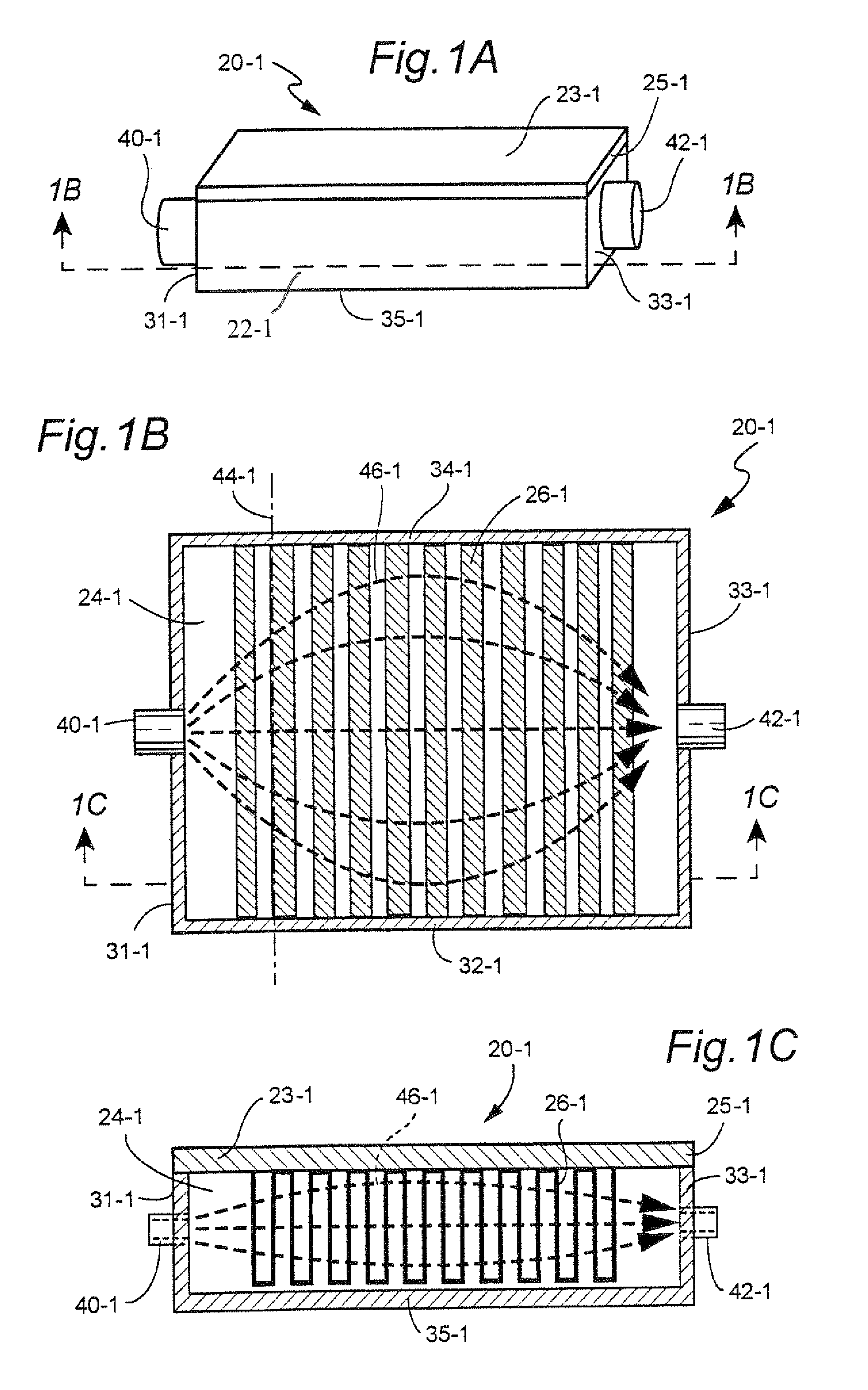
[0071]In like manner as some of the other embodiments illustrated herein, the cover 22-1 is essentially a parallelepiped. In fact, the cover 22-1 of the first embodiment is a rectangular parallelepiped having one open face. As such, the cover 22-1 has five walls. The walls of the cover 22-1 include side walls 31-1, 32-1, 33-1, and 34-1, as well as cover wall 35-1. The cover wall 35-1 lies in a plane which is parallel to thermal transfer base 25-1. When the thermal transfer device is assembled, the open face of cover 22 is closed by thermal transfer base 25-1. FIG. 1A, FIG. 1B, and FIG. 1C show the thermal transfer device 20-1 with thermal transfer base 25-1 surmounting the cover 22-1.

[0072]The thermal transfer base 25-1 can be secured to cover 22 by any suitable fasteners or adhesives such as, e.g., threaded fasteners. FIG. 1B shows the interior of the chamber looking up from cover wall 35-1 toward the underside of thermal transfer base 25-1, thereby also permitting a view of the th...

third embodiment

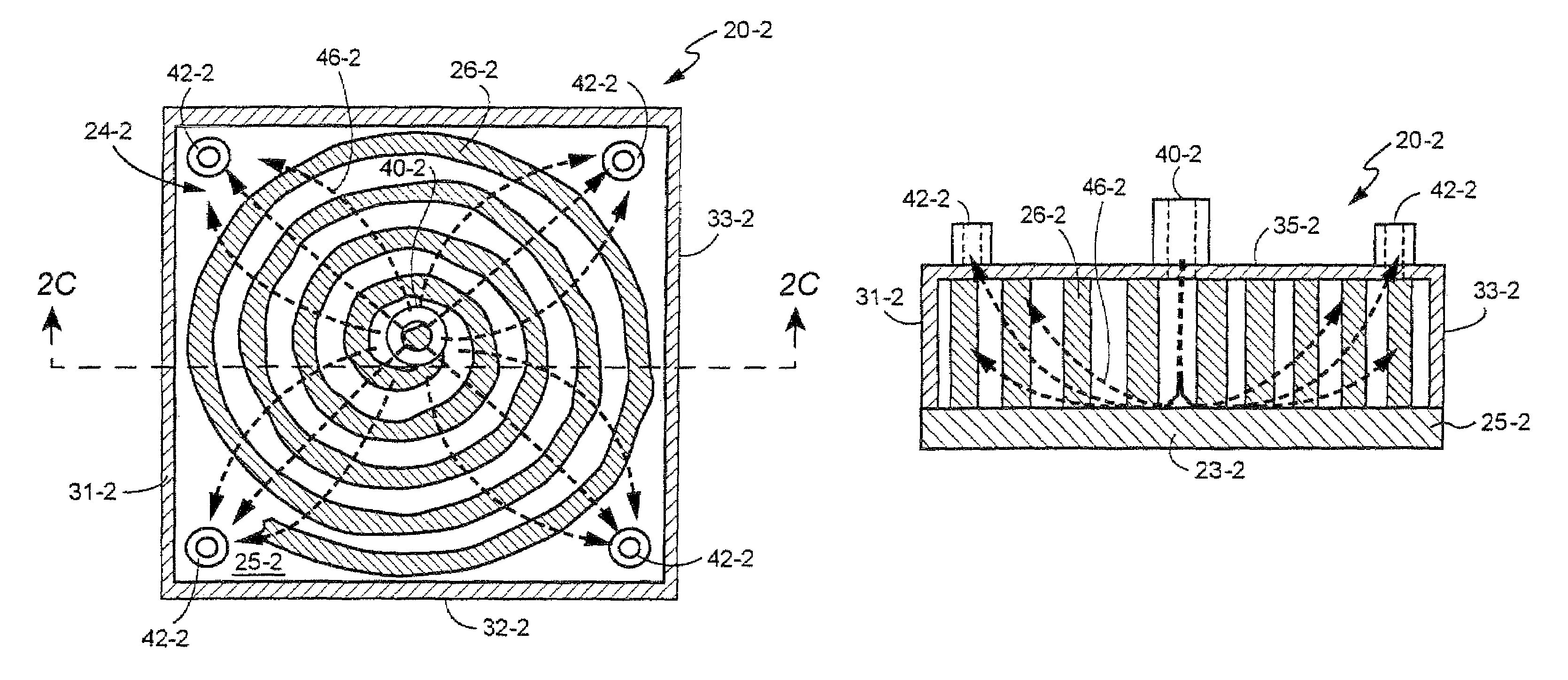
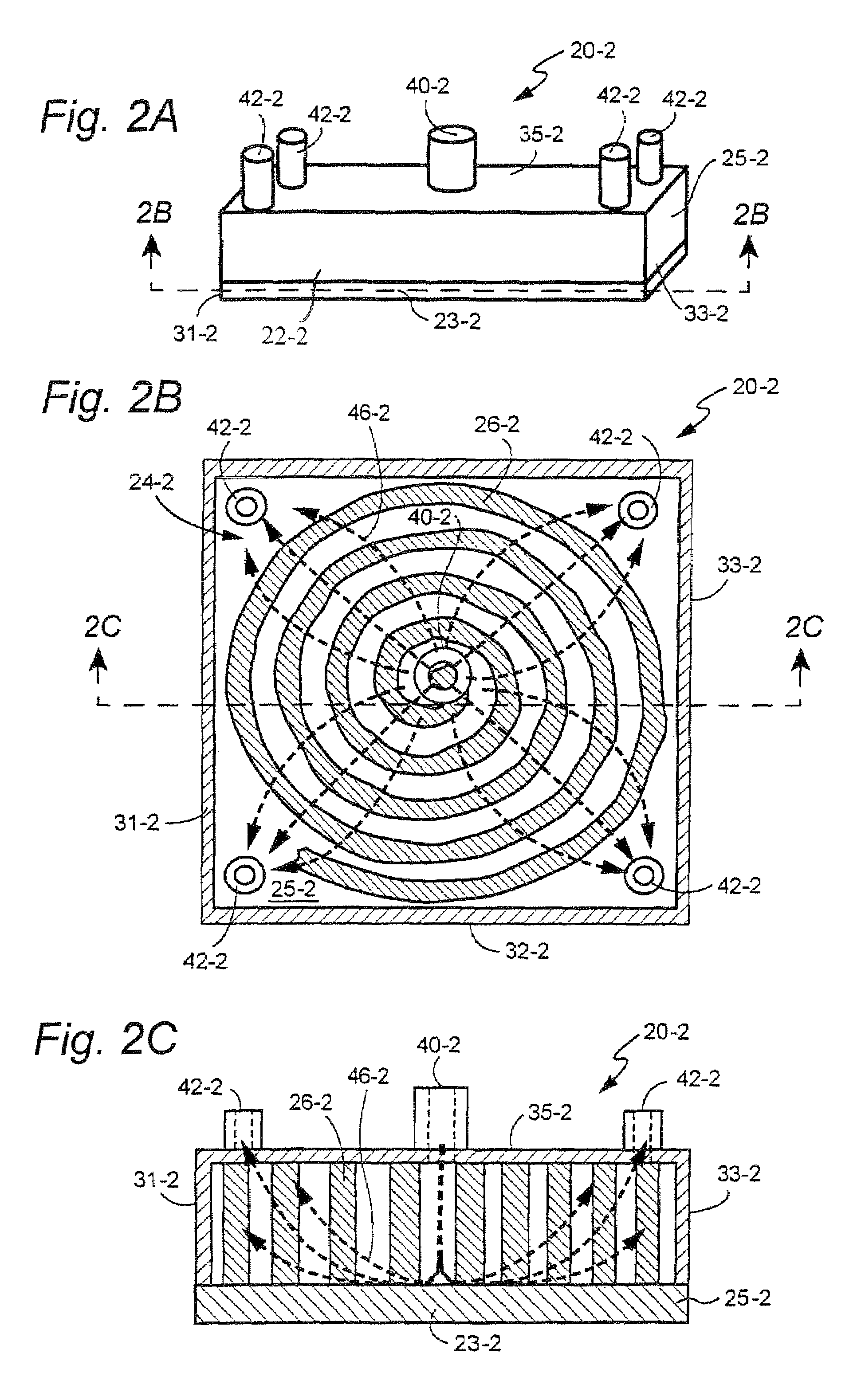
[0088]As in the other embodiments, the thermal mesh structure 26-3 is situated in the chamber 24-3 to transfer thermal energy acquired from the thermal transfer base 25-3 to the fluid in the chamber 24-3 as the fluid first impinges upon thermal transfer base 25-3 and then is pumped through interstices of the thermal mesh structure 26-3. As mentioned previously, preferably the thermal mesh structure is formed integrally with or bonded to the thermal transfer base 25-3 (e.g., diffusion bonded in the same or different operation in which the wires of the thermal mesh structure are bonded). As shown in FIG. 3C, the thermal mesh structure 26-3 of the third embodiment has an essentially circular configuration within the chamber, and preferably is configured to comprise plural concentric rings within the chamber.

[0089]FIG. 3D shows a variation of the third embodiment in which inlet 40-3 of the housing is an opening through which a nozzle 47 extends. In particular, nozzle 47 extends through ...

fourth embodiment

[0094]Although the mating of cover 22-4 and base assembly 23-4 is not illustrated for the fourth embodiment, it will be appreciated that cover 22-4 fits over base assembly 23-4 to define a chamber in similar manner as previously described embodiments. To this end, fastener holes are provided in aligned fashion proximate corners of both thermal transfer base 25-4 and cover 22-4. The cover 22-4 is essentially a square parallelepiped having an open face and has five walls including side walls 31-4, 32-4, 33-4, and 34-4, as well as cover wall 35-4. The cover 22-4 fits over thermal transfer base 25-4.

[0095]In the fourth embodiment, the cover wall 35-4 of cover 22-4 includes both a single inlet 40-4, as well as plural (e.g., four) outlets 42-4 (see FIG. 4D). In the illustrated version of the second embodiment, the single inlet 40-4 is centrally located, while each of the four outlets 42-4 are situated in (e.g., proximate) a separate corner of cover wall 35-4. The inlet 40-4 communicates t...


PUM

PropertyMeasurementUnit
diameteraaaaaaaaaa
diameteraaaaaaaaaa
diameter D40aaaaaaaaaa

Abstract

A thermal transfer device (20) comprises a housing having a base assembly (23) and a cover (22). The base assembly (23) comprises a thermal transfer base (25) and a fluid-porous, thermally conductive mesh structure (26). The thermal transfer base (25) and the cover (22) cooperate to define a thermal transfer chamber (24). The thermally conductive mesh structure (26) is configured and positioned in the chamber (24) to provide a tortuous, thermal conduction path for fluid (e.g., a coolant) which turbulently travels from an inlet (40) of the chamber to one or more outlets (42) of the chamber (24). In some embodiments, the mesh structure comprises wires which are fused by diffusion bonding into a mesh, in other embodiments the mesh comprises a metallic wool. Within the chamber the mesh structure (26) can have various configurations for providing an exposure interface between fluid pumped through the chamber and the mesh.

Description

[0001]This application is a continuation-in-part of U.S. patent application Ser. No. 10 / 815,992, filed Apr. 2, 2004 now abandoned, entitled “DIFFUSION BONDED WIRE MESH HEAT SINK”, which is incorporated herein by reference in its entirety.BACKGROUND[0002]1. Field of the Invention[0003]This invention pertains to cooling or heat dissipating devices (e.g., thermal transfer devices) such as heat sinks and thermal exchangers, and particularly to devices which accomplish thermal transfer by a circulating fluid.[0004]2. Related Art And Other Considerations[0005]Various types of equipment create or release heat during operation. In some cases the heat can be injurious to the equipment or its environment (e.g., other equipment or components in proximity to the heat-generating or heat-releasing equipment). Accordingly, attempts have been made in some such cases to cool the equipment and / or its environs. Common cooling techniques include circulation of a cooling fluid around or near the source ...

Claims


Application Information

Patent Timeline
Patent Type & Authority Patents(United States)
IPC IPC(8): F28F7/00F28D15/00H05K7/20F28F3/02F28F13/00H01B7/42H01L23/34H01L23/373H01L23/473
CPCF28F3/022F28F13/003H01L23/3733H01L23/473H01L2924/0002H01L2924/00F28F3/12
Inventor EAST, W. JOEWEISS, ELLIOT
Owner PAR TECH
Why Eureka
Try Eureka